background image

57

C    Electrical interface pinout

Figure 42  

C/3 electrical interface pins

Table 13  

C/3 electrical interface pin descriptions

C

B

A

10


9


8


7


6


5


4


3


2


1


30 pin DIN41612 male C/3 type

Pin #

Signal

Description

A1

Module OK

Low: module enable low OR module power low
High: module power high

A2

RS485-

Negative/inverted RS485 differential data signal

A3

Interlock loop+

Positive connection of interlock loop. Should be connected to Interlock loop- (pin no. 4) to enable 
emission from the system.

A4

Interlock loop-

Negative connection of interlock loop. Should be connected to Interlock loop+ (pin no. 3) to enable 
emission from the system.

A9

N/C

A10

N/C

B1

Service

NKTP Technical Support

B2

Service

NKTP Technical Support

B3

Service

NKTP Technical Support

B4

N/C

B9

AGND

Analog ground for amplitude and wavelength modulation signals.

B10

AGND

Analog ground for amplitude and wavelength modulation signals.

C1

Emission

Collector output with internal 240 Ω resistor in series. The output is high when the amplifier emission 
is ON. An LED anode can be connected directly to this pin and the Cathode to GND to indicate 
emission externally.

C2

RS485

Positive/non-inverted RS485 differential data signal

C3

Enable

Logic input that permits emission when a high (5V) i is applied. During emission if Enable is set low, 
emission is shut off.

C4

Enable logic input

Logic input that permits emission when a high is applied. If during emission the input is set low, 
emission is shut off. This control input is for personal safety and is designed with redundancy within 
the module.

C9

N/C

C10

N/C

A5, A6, 
B5, B6, 
C5, C6

GND

0 volt / ground

A7, A8, 
B7, B8, 
C7, C8

12V

12 volt supply voltage for the module.

Summary of Contents for Koheras BOOSTIK

Page 1: ...Item 800 631 01 Koheras BOOSTIK PRODUCT GUIDE Narrow linewidth laser amplifier...

Page 2: ...amplifier housed in a line card form factor Koheras BOOSTIK 200 mW 1550 nm 200 mW narrow linewidth line card amplifier housed in a line card form factor Koheras BOOSTIK 200 mW 1064 nm 200 mW narrow li...

Page 3: ...BOOSTIK is a module designed to be fitted to and as part of a complete laser system Target Audience This guide is for technical personnel involved in the selection planning and deployment of lasers in...

Page 4: ...4 Appendices The guide includes multiple appendices including specifications support contact details connector pin assignments error codes and a control software installation procedure...

Page 5: ...ts additional information related to the associated topic and or provides links or the name of the NKTP guides describing the additional information Caution Alerts you to a potential hazard that could...

Page 6: ...l 16 Rear panel 18 CONTROL GUI 19 Generic UI and NKT Photonics SDK 19 Enabling emission 19 Status LEDs 20 Chassis labels 21 BOOSTIK labels 21 2 Installation 23 Safety 23 Passive cooling 23 Rear panel...

Page 7: ...33 CONTROL settings 33 CONTROL menu 35 Key Updater tool 35 Log download tool 36 Extensions overview 38 Device monitor 39 Application log 40 Control panel 41 Power 41 Module overview 41 Toggling and so...

Page 8: ...raphing 50 A Specifications 53 B Service and Support Information 55 Servicing the laser 55 Opening the module 55 WARRANTY VOID IF REMOVED label 55 Support contact details 56 Support website 56 C Elect...

Page 9: ...Monitor parameters 39 Table 6 Module overview fields 42 Table 7 Generic user interface registers 45 Table 8 Optical specifications 53 Table 9 Power consumption 53 Table 10 Mechanical dimensions 53 Tab...

Page 10: ...10...

Page 11: ...nt free 26 Figure 12 Optical fiber cleaning tool 27 Figure 13 CONTROL panels and menu 29 Figure 14 Panel dragged to a new location in the main window 30 Figure 15 Panels dragged outside the main windo...

Page 12: ...ure 33 Stage one input monitor 48 Figure 34 Pump temperature 49 Figure 35 Pump 1 current 49 Figure 36 Error and status tab 50 Figure 37 Graphing tab 51 Figure 38 Mechanical dimensions front panel with...

Page 13: ...13 PROCEDURES Procedure 1 Relocating panels 30 Procedure 2 Using the Key Updater tool 36 Procedure 3 Using the Log Downloader 37 Procedure 4 Installing CONTROL 61...

Page 14: ...14...

Page 15: ...ber fitted with a standard FC APC connector The amplifier module operates in the 1060 1075 nm or 1545 1565 nm wavelength range Depending on the variant the amplifier is designed to extend the output p...

Page 16: ...ollowing states Power the supply voltage status Interlock interlock circuit open closed not OK OK Emission the laser emission status enabled or disabled Status the module stability status For more inf...

Page 17: ...COUSTIK the module is fastened securely using four M4 x 0 7 mm pitch screws Figure 3 Inserting a BOOSTIK into an ACOUSTIK shelf Input fiber connector The optical input of a BOOSTIK is a threaded FC AP...

Page 18: ...rear Figure 4 BASIK rear panel layout Main electrical Interface Caution The main electrical interface is a 30 pin male C 3 connector located on the rear panel of the module The interface includes pin...

Page 19: ...eneric User Interface or Generic UI is an application intended for setting and reading BOOSTIK module registers The module uses registers to either set its parameters or indicate a condition The regis...

Page 20: ...Information Koheras BOOSTIK 200 mW Laser Safety Handling and Regulatory Information Emission Interlock Status Power LED Name Condition Description Power ON Green DC Voltage at the DC power input pins...

Page 21: ...arning Safety information alert indicating this area of the laser is near a source of dangerous laser emissions Manufactur ing Manufacturing information including address part and serial number and da...

Page 22: ...ssification emission hazards 4 Product identification side panel WARNING INVISIBLE LASER RADIATION AVOID EXPOSURE TO BEAM CLASS 4 LASER COMPONENT MAXIMUM OUTPUT POWER 5W WAVELENGTH 900 2100 nm DESIGNA...

Page 23: ...be exposed to corrosive agents or excessive moisture heat or dust Caution Table 11 in Appendix A lists the specifications for the BOOSTIK operating en vironment Rear panel surface The rear panel surfa...

Page 24: ...able to firmly mount the module for proper heat conduction Figure 8 Left side panel heat conduction surface Example side panel cooling Figure 9 shows a custom passive cooling block mounted on the left...

Page 25: ...standard optical table Custom installation rules Allow for proper ventilation and cable access Do not store or place anything on the top panel of the amplifier Ensure the ambient operating temperatur...

Page 26: ...he output aperture of the BOOSTIK is a fiber with a optical connector At the tip of the connector is a fiber facet where Class 3b or Class 4 emission are present Without proper care the facet is easil...

Page 27: ...ber facet is damaged the connector must be re polished before operating the laser Failing to do so could result in incorrect measurements usage or even damage to the laser unit itself Caution The conn...

Page 28: ...etector card to check the beam shape Caution If you do not obtain a good beam shape after polishing the connector may be damaged Return the laser to NKT Photonics for repair Note that this type of rep...

Page 29: ...Status panel on page 32 Menu items Four drop down menus with multiple functions CONTROL menu on page 35 Control panel The control panel displays the input power received and controls the output power...

Page 30: ...panels to be displayed A blue check mark indicates the panel is displayed Action 1 Left click hold the top title bar of any panel 2 While holding the left mouse button down drag the panel to another...

Page 31: ...M or Ethernet port your ACOUSTIK shelf is using to connect CONTROL to the ACOUSTIK The Control and Status panels are displayed when the laser connects to CONTROL Note To connect the PC to CONTROL refe...

Page 32: ...evice selector panel Status panel The Status Panel provides status indicators error messages system information emission control function and a settings menu Figure 19 Status panel indicators Status i...

Page 33: ...s see View on page 34 Measurements The system temperature is displayed Note Measurements are only displayed if the option is checked in the View menu see View on page 34 Emission button The Emission b...

Page 34: ...he User text field input an alphanumeric text string to name the module The string is displayed next to the module icon in the Device Selector panel Figure 21 View settings Setting Item Function See V...

Page 35: ...e configured device connections to connect control to Disconnect disconnects the currently connected device from CONTROL Refer to the included CONTROL user help under Help Show Instruction Manual Tool...

Page 36: ...ated log download mode by enabling a collect log function Fast log vs slow log Both fast and slow log types collect the same data from the device The difference between the two logs is their polling r...

Page 37: ...ected for each module Logs are collected from each module The total collected percentage is displayed for the module s logs 3 To download and save a log file to the CONTROL PC right click the percenta...

Page 38: ...hort description of the release notes as seen in Figure 23 hover the mouse pointer over the Release notes text Note Multiple extensions for a wide range of NKTP lasers types and accessories are typica...

Page 39: ...bled Status bits The actual status bits read from the connected module Error code The actual error code read from the connected module Access Protected Locked status of the module FW Ver The device mo...

Page 40: ...g the buttons in the upper left corner Figure 24 Serial monitor The panel is enabled by placing a check mark on the Window drop down menu next to the Application Log item To close the panel click on t...

Page 41: ...l The level can be set from 10 to 100 of the maximum rated power You can additionally key in the power level directly by using the text input field at the upper right corner of the slider control Note...

Page 42: ...evel set with CONTROL in mW Actual power mW Measured power level in mW Power setpoint dBm Power level set with CONTROL in dBm Actual Power dBm Measured power level in dBm Emission Displays status of m...

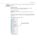
Page 43: ...new location to change the order of the fields in the header Togging fields on and off Right clicking on any of the fields in the header displays the menu shown in Figure 27 To remove a field from th...

Page 44: ...Module overview 44...

Page 45: ...ment SDK Instruction Manual The manual is installed when the SDK installer is run SDK installer The SDK installer including instructions is available at the following URL https www nktphotonics com la...

Page 46: ...der the Control tab Output power setpoint Input the optical output setpoint power level in mW or dBm For setting the power using mW units use register 22 and for using dBm units used register A0 Figur...

Page 47: ...30 Enabling emission Setup bits Register 31 Setup bits configures the laser amplifier to operate in either current or power mode Set as follows 0000 Power mode 0001 Current mode Figure 31 Setting the...

Page 48: ...y monitor registers under the Readings tab Stage one input monitor Register 10 in the Readings tab displays the input power in mW received at the optical input of the laser amplifier Before enabling t...

Page 49: ...34 Pump temperature Heat sink temperature Register 1C of the Readings tab displays the a temperature measurement from a sensor within the module near its rear passive cooling surface Figure 35 Pump 1...

Page 50: ...For a list of error codes and their descriptions see Table 14 on page 59 Figure 36 Error and status tab Graphing As shown in Figure 37 you can graph the values of selected parameters by clicking on t...

Page 51: ...51 Graphing Figure 37 Graphing tab X axis setting Y axes settings...

Page 52: ...Graphing 52...

Page 53: ...i Size H x W x D 92 x 220 x 39 mm 3 62 x 8 66 x 1 54 in Weight 1 kg 2 2 lb Operating Temperature internal case 15 C to 55 C 59 F to 131 F Storage Temperature 20 C to 60 C 4 F to 140 F Operating Humidi...

Page 54: ...54 Figure 38 Mechanical dimensions front panel without faceplate Figure 39 Mechanical dimensions side panel Figure 40 Mechanical dimensions rear panel 2...

Page 55: ...ontains electro static discharge ESD sensitive compo nents To avoid permanent ESD damage use ESD protection precautions when han dling it Always connect any earth point to a ground earth within your f...

Page 56: ...TIK laser or its accessories contact NKT Photonics through our support website below Support website 1 Go to https www nktphotonics com lasers fibers support technical support and customer service 2 S...

Page 57: ...ical Support B4 N C B9 AGND Analog ground for amplitude and wavelength modulation signals B10 AGND Analog ground for amplitude and wavelength modulation signals C1 Emission Collector output with inter...

Page 58: ...58 2...

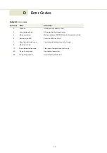
Page 59: ...low 4 Memory problem Memory problem EEPROM read write operation failed 6 Bad emission LED Emission LED circuit fault 7 Board temperature range Control board temperature out of range 8 Module disabled...

Page 60: ...60 2...

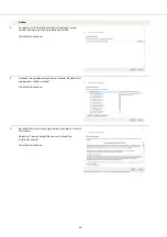
Page 61: ...https www nktphotonics com lasers fibers support software drivers Follow the steps in Procedure Procedure 4 Installing CONTROL Action 1 On the PC launch the installer package and then click the Run bu...

Page 62: ...utton Click Next to continue 4 Uncheck the components you do not require By default all components will be installed Click Next to continue 5 ReadtheEnd UserLicenseAgreement andselect Iaccept the lice...

Page 63: ...am short cuts Use the default name or enter a new name for the folder Click Next to continue 7 Check the box to create a desktop shortcut to access Control Click Next to continue 8 Check the Silicon L...

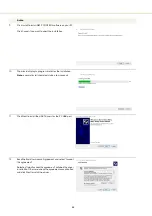
Page 64: ...e installation Note a normal install should only take a few seconds 11 Click Next to install the UART drivers for the PC USB port 12 Read the End User License Agreement and select I accept this agreem...

Page 65: ...installed 14 The Silicon Labs drivers is installed successfully Click Finish to end the installation wizard 15 CONTROL is now installed Check the Run box to launch CONTROL when the Finish button is cl...

Page 66: ...66...

Page 67: ......

Page 68: ...1 Koheras BOOSTIK Product Description Revision 1 0 09 2021 W 10456...

Reviews: