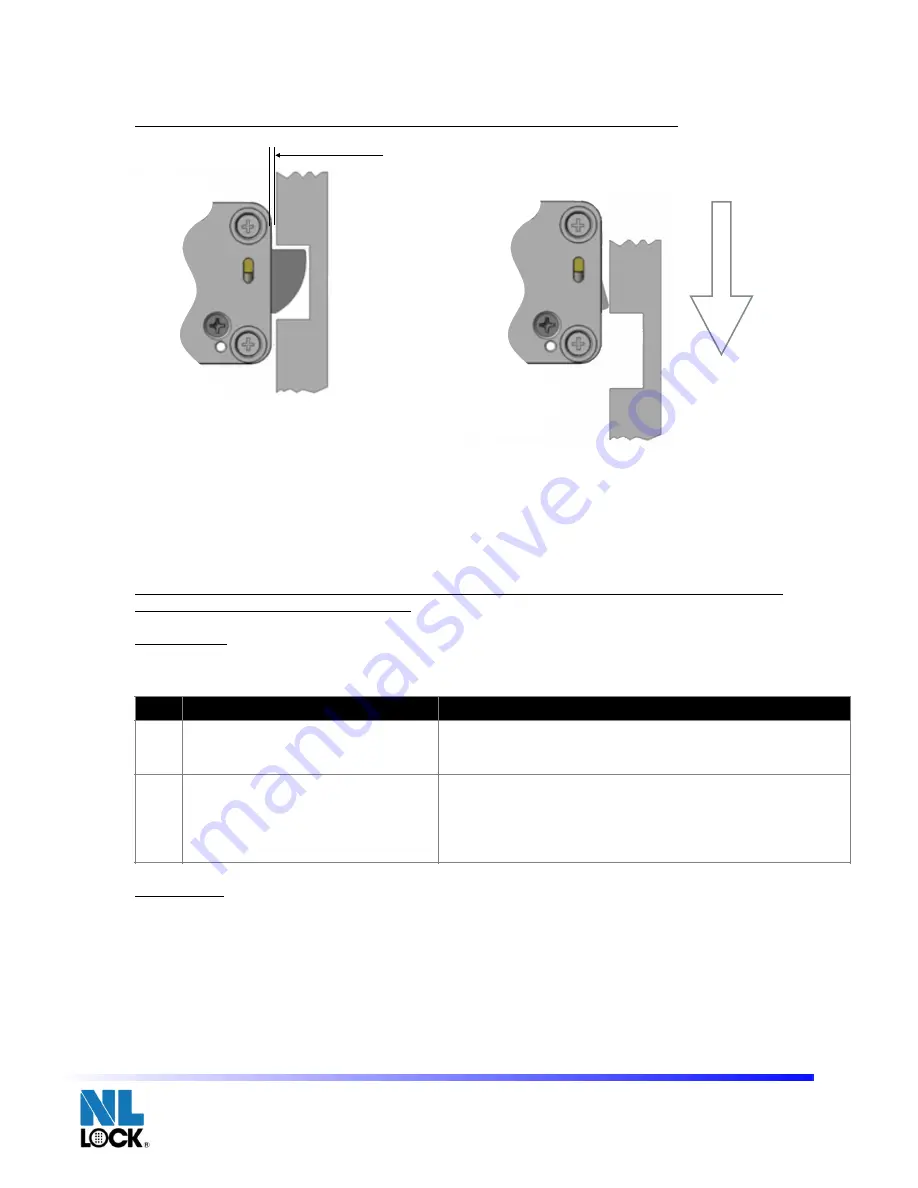
BOLTWORK REQUIREMENTS and MOUNTING SPECIFICATIONS
If the Duet Rotobolt lock is used in conjunction with another lock, the boltwork must be constructed in a
way that the Universal secures first.
In the LOCKED position the distance between the Universal bolt and the boltwork part that is moving the
lock bolt should be approximately 1 mm.
Only use NL LOCK supplied screws (M6) to mount the lock. Lock has to be mounted on secure storage metal
(preferred steel) units only. Tighten the screws securely so the lock body is attached firmly to the mounting
surface. Use of screw locking glue (i.e. Loctite) is recommended.
Security relevant parts of a HSL should not be accessible to unauthorized persons when the door of the
secure storage unit to which it is fitted is open
Test Electronics
Like all locks from NL LOCK this unit includes a unique feature to functionally test the electronics:
Function #5
Functional Test
•
Enter code (i.e. 1-2-3-4-5-6). The lock emits a double signal for the correct code.
•
Turn boltwork handle towards OPEN position.
The bolt rotates into the housing. Bolt must move freely.
•
Turn handle towards Locked position.
The lock bolt must fully extend and secure.
•
Make sure there is an air space on all sides of the lock bolt when the safe’s boltwork is fully thrown
into locked position.
IMPORTANT: Perform the functional test several times before locking the safe door.
RR40•20 Technical Manual rev. 170528
© 2017 Lock Technology Page
!
of
!
2
4
STEP
TASK
REMARK
1
Press and hold [5] until a double
signal sounds and the light stays ON.
2
Enter the all keys in exactly this
sequence:
[1]-[2]-[3]-[4]-[5]-[6]-[7]-[8]-[9]-[0]
Push buttons slowly so you recognize the signaling of the
lock. A double signal indicates that the keypad and the lock
communicate and perform properly.
A long signal indicates that the electronics may be damaged.
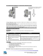
Lock bolt operations only allowed as described
into the drawing and max load should not
exceed 1KN.
min 1.5 mm.

