background image

Acuity Brands  |  One Lithonia Way  Conyers, GA  30012  Phone: 800.535.2465  www.acuitybrands.com/nLight

© 2019-2020 Acuity Brands Lighting, Inc. All rights reserved.  Rev. 05/15/20

nDTC

2 of 4

WIRING — Wall-Mount version

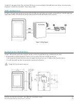
Figure 1 - Wiring Diagram

A 15-24 VDC or VAC power supply can deliver power to the nLight® nDTC via the polarity insensitive terminal connections on the back of the unit. The PS 150 version power 

supply is recommended, as it conveniently mounts through a knock-out on the back of the junction box where the unit is mounted. 

The nLight nDTC is equipped with two RJ-45 ports to facilitate CAT5e daisy-chain connection with other nLight-enabled devices, and a set of power terminals where low 

voltage power is connected (from the provided PS 150 power supply module).

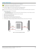
Mounting Instructions — Wall-Mount Version

• 

The device should be installed approximately 6” (15cm) from a corner, to provide sufficient access to the faceplate release tabs.

• 

Allow for proper clearance around the device’s enclosure and wiring terminals to provide easy access for hardware configuration and maintenance.

• 

Orient the device with the ventilation slots towards the top to permit proper heat dissipation.

The nLight® nDTC has been designed for ease of installation. However, certain conditions apply when choosing a suitable location for the device:

The nLight® nDTC is not designed for outdoor use.

Summary of Contents for nDTC

Page 1: ...to an ARP panel the device communicates with an nLight Wired network and supports up to 127 digital devices in an nLight control zone FEATURES Create and control up to 32 schedules Normal Holiday Controls up to 127 nLight devices Password protected configuration Optional password protected lock out Proximity screen sensor for auto wake up Slim and compact form factor 3 5 full color responsive capa...

Page 2: ...cilitate CAT5e daisy chain connection with other nLight enabled devices and a set of power terminals where low voltage power is connected from the provided PS 150 power supply module Mounting Instructions Wall Mount Version The device should be installed approximately 6 15cm from a corner to provide sufficient access to the faceplate release tabs Allow for proper clearance around the device s encl...

Page 3: ...insert them through the central hole of the back plate 4 Make sure that the mounting surface is flat and clean 5 Screw the back plate onto the electrical junction box 6 Plug the wire s into the connector s Gently push excess wiring back into the wall 7 Reattach the front plate and make sure it clips tightly into place Tighten the security screw 8 Upon restoring power unit will begin discovering co...

Page 4: ...ent Equipment FCC Rules Part 15 Subpart B Class B Mechanical Dimensions 5 18 H x 3 37 W x 0 75 D 131 5mm x 85 5mm x 19mm Mounting Single Gang Box or Low Voltage Ring Connection Type RJ 45 nLight Network Ports 2 Low Voltage Terminals Color White Black Environmental Warrantied Operating Temperature Standard 32 F to 122 F 0 C to 50 C Relative Humidity Up to 90 Non Condensing Standards Rating RoHS Gen...

Reviews: