
Acuity Brands | One Lithonia Way Conyers, GA 30012 Phone: 800.535.2465 www.acuitybrands.com/nLight
© 2019-2020 Acuity Brands Lighting, Inc. All rights reserved. Rev. 05/15/20
nDTC
3 of 4
Installation — Wall-Mount Version
1. Turn circuit breaker to
OFF
position, or remove fuse(s), and test that power is off before installation process.
Never wire any electrical device with power turned on. Wiring while
HOT
may cause permanent damage to this device and other equipment and void warranty.
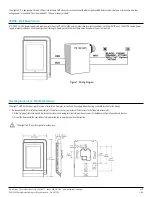
2. Remove the front cover of the device from the mounting plate:
a. Remove the security screw
b. Using an appropriately sized tool, press in the two (2) release tabs on the sides of the device and pull the front cover out from the bottom. See Figure 2 for
security screw and release tab locations.
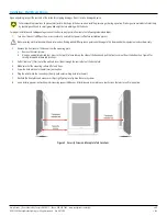
3. Pull all cables 6” (15cm) out of the wall and insert them through the central hole of the back plate.
4. Make sure that the mounting surface is flat and clean.
5. Screw the back plate onto the electrical junction box.
6. Plug the wire(s) into the connector(s). Gently push excess wiring back into the wall.
7. Reattach the front plate and make sure it clips tightly into place. Tighten the security screw.
8. Upon restoring power, unit will begin discovering connected devices. After discovery is complete, use touch screen features to confirm operation.
Upon unpacking, inspect the contents of the carton for shipping damages. Do not install a damaged device.
Take reasonable precautions to prevent electrostatic discharge to the device when installing, servicing or during operation. Discharge accumulated static electricity
by touching one’s hand to a well-grounded object before working with the device.
For proper installation and subsequent operation of the device, pay special attention to the following recommendations:
Figure 2 - Security Screw and Faceplate Tab Locations


