iTerm Rack Kit Installation Guide
06/01/06 Rev 1.0
Page 5 of 10
SECTION
3
Cable Connections
The terminal may be configured to communicate using either a serial RS232 connection or an
Ethernet telnet connection. Although it is possible to connect both RS232 and Ethernet cables, it is
only possible to use one type of connection at any time (depending on configuration defined in
terminal set up).
The Ethernet network connection may be used to connect to any 10Mb compatible Ethernet host
adapter. However the Ethernet connection is most suited for use with RSC (Remote System Control)
Ethernet ports since these provide the same functionality as serial (ttya) console ports.
If connecting a serial RS232 cable to the server, it is advisable to power down the server first.
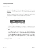
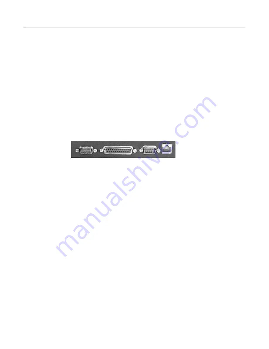
The rear of the terminal tray has the following connections.
SERIAL 2 PARALLEL SERIAL 1 10BASE T
•
Serial 2 and Parallel
The terminal supports a local printer which can be connected to a serial (male 9-pin D connector)
or parallel (female 25-pin D connector) interface. Printer cables are not included with the terminal,
and specific printers have not been qualified for this connection.
•
Serial
1
This is a male 9-pin D connector port which should be used for a serial RS232 console
connection. The included cable can be used to connect this port to a female 25-pin D connector
console port. The included 25-pin to 9-pin adapter should be used in conjunction with this cable
when connecting to a male 9-pin D connector console port.
If your server has an RJ45 serial (RS232) port, connect the included 9-pin to 25-pin adapter
directly to the SERIAL 1 port at the rear of the terminal. Then use the RJ45 cable and RJ45 to
DB25 adapter (part number 530-2889) which are included with the server to connect to the
terminal.
When the terminal looses power or is powered off, a ‘break’ may be generated on the RS232 (SERIAL 1) host port (as is common with
most general purpose terminals).


