5
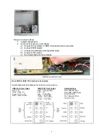
USB Diagram IEEE 1394 Diagram
Front Audio (AC 97) connection Tips:
First, find the MIC and GND pin, connect the MIC & GND connector fist, then, the SR connector must on the Pin
5 & 6, face the same label direction of the MIC & GND connector, plug the SR in, same to the SL on Pin 8 & 9.
Plug the white NC single pin connector to Pin 7.
Note:
There is no HD Audio connector from this model yet.
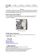
Connect the Power Button “PWR” & “RESET” cable
to the motherboard front panel jumper
See Motherboard User Manual for location and
connection. And see above referenced picture.
Connect Card Reader USB cable
See Motherboard User Manual for onboard USB
port location and connection. And see above
referenced picture.
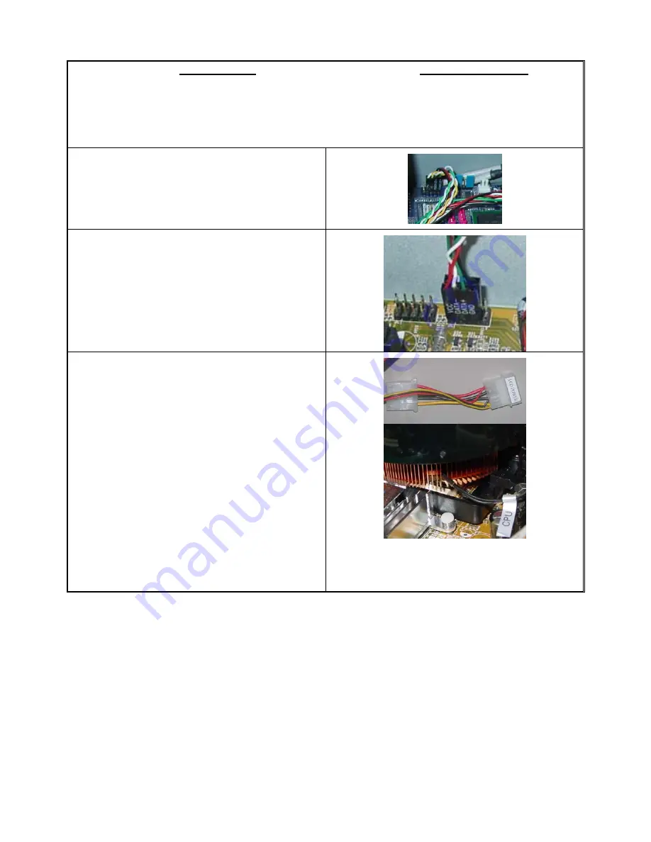
Connect LCD Cables (Some of these steps follow
after CPU & Cooler installation)
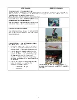
1. Use the orange tape in the accessory bag to tape
the CPU heat sensor to the CPU heatsink so that
LCD can display the CPU temperature accurately
2. Connect the CPU heatsink fan to the LCD “CPU
Fan” adapter, if your motherboard has the auto fan
speed control function (base on CPU temp); plug
the extension cord to the motherboard fan
connector. In this case, the LCD will only display
fan speed, no fan speed control will be available via
the front knob.
3. Connect the “PWR” LCD power cord to the power
supply like connecting the case fan. This
connection will provide power to:
Power button LCD light
LCD
module
<<Periodically check sensor head placement is
recommended to ensure accurate CPU Temperature
Reading>>


