3
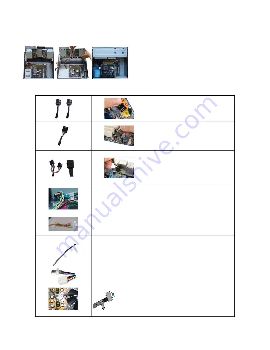
3. Install Optical Drive Bracket back to the case
4. Put the bracket in the slot hole that will hold it in 110 degree angle, connect cables and the power
cords for the hard drive and optical drive
5. Lock the bracket
6. Connect power supply cords
Step 4: Connect Cables
Following your motherboard user guide to:
Connect Card Reader & USB Ports
z
There are two 10 pins USB connectors.
z
Match the pin label (on connector) and your board
user guide USB port layout for accuracy.
Connect IEEE 1394 Port
z
There is one 10 pins 1394 connector
z
Match the pin label (on connector) and your board
user guide 1394 port layout for accuracy. (Not all
board has onboard 1394 port, leave It unplug if
you don’t have it)
Connect HD Audio and e SATA Port
z
There is one SATA connector, connect it to your
onboard SATA port
Check your board to see if it has HD onboard port that
supports HD audio
z
If yes, plug the HD connector to your HD onboard
audio port
z
If no, plug it to your AC 97 chipset onboard audio
port using the Y tale connector
z
Connect Power Switch connector to your onboard port
z
Connect Reset Switch connector to your onboard port
z
Connect HDD Power Switch connector to your onboard port
Connect LCD PWR Connector
Connect it directly to the equipped Power Supply 12V connector. Like
connecting the case fan.
LCD Module Cables
Use tape to secure the CPU heat sensor around the heatsink area for displaying
CPU Temp on the LCD. See left header
Connect the CPU Cooler Fan to the CPU FAN connector so that CPU Fan Speed can be
displayed and controlled by LCD.
If you want motherboard to control the CPU fan speed, simply connect the extension
connector from the LCD CPU Fan to the motherboard Fan header. Motherboard will take
control priority and LCD will only display fan speed.
<<Periodically check sensor head placement is recommended to ensure
accurate CPU Temperature Reading>>
The C/F switch enables you to set the CPU temp display format when
installing the system. Down – F, Up - C


