User Manual 65
User Manual 64
Symbol and Description of M Type Control unit
No.
1
2
3
4
5
6
7
8
9
10
11
12
13
14
15
16
17
18
19
20
21
22
23
24
25
26
27
28
29
30
31
32
33
34
35
36
37
Description
Ground-fault, A, B, C and N phases
Current and time setting of long-time delay
Current and time setting of short-time delay
Ground-fault current and time setting
Instantaneous current setting
Reverse time
Neutral protection setting
Current unbalance protection setting
Thermal memory setting
trip simulation setting
Communication setting
Trip record view
Alarm record view
Position change record view
View of LSIG setting
Current unbalance
Test setting of LSI current protection
Vector and ground-fault protection test setting
Test confirmation status
Modbus-RUT address setting
Modbus-RUT address selection
Modbus-RUT baud rate setting
Trip status
Running status
Normally ON: setting status
Alarm status
No information
Open
Closed
Magnetic break
CT break
Action rejection
LSIG curve. The full display means normal operation. In case of fault tripping, the corresponding segment will flash.
"ESC" button identification
"Down" button identification
"Up" button identification
"OK" button identification
Symbol
Lg L1 L2 L3 LN
IR= Tr=
Isd= tsd=
Ig= tg=
Ii=
F0
F1
F2
F3
F4
F5
F6
F7
F8
U.
3PHS
gdr
A.-
bPS means
TRIP
RUN
SET
ALM
NULL
OPEN
CLSE
E1
E2
E3
The LED of the control unit is a customized module. The symbols are described in the following
table for the convenience of users.
Operating Instructions for M Type Control Unit Interface
The M type control unit includes the following interfaces: default interface, setting interface, view interface, and trip interface.
Default interface is measurement status, all fault indicators are OFF, and the current of each phase is displayed cyclically.
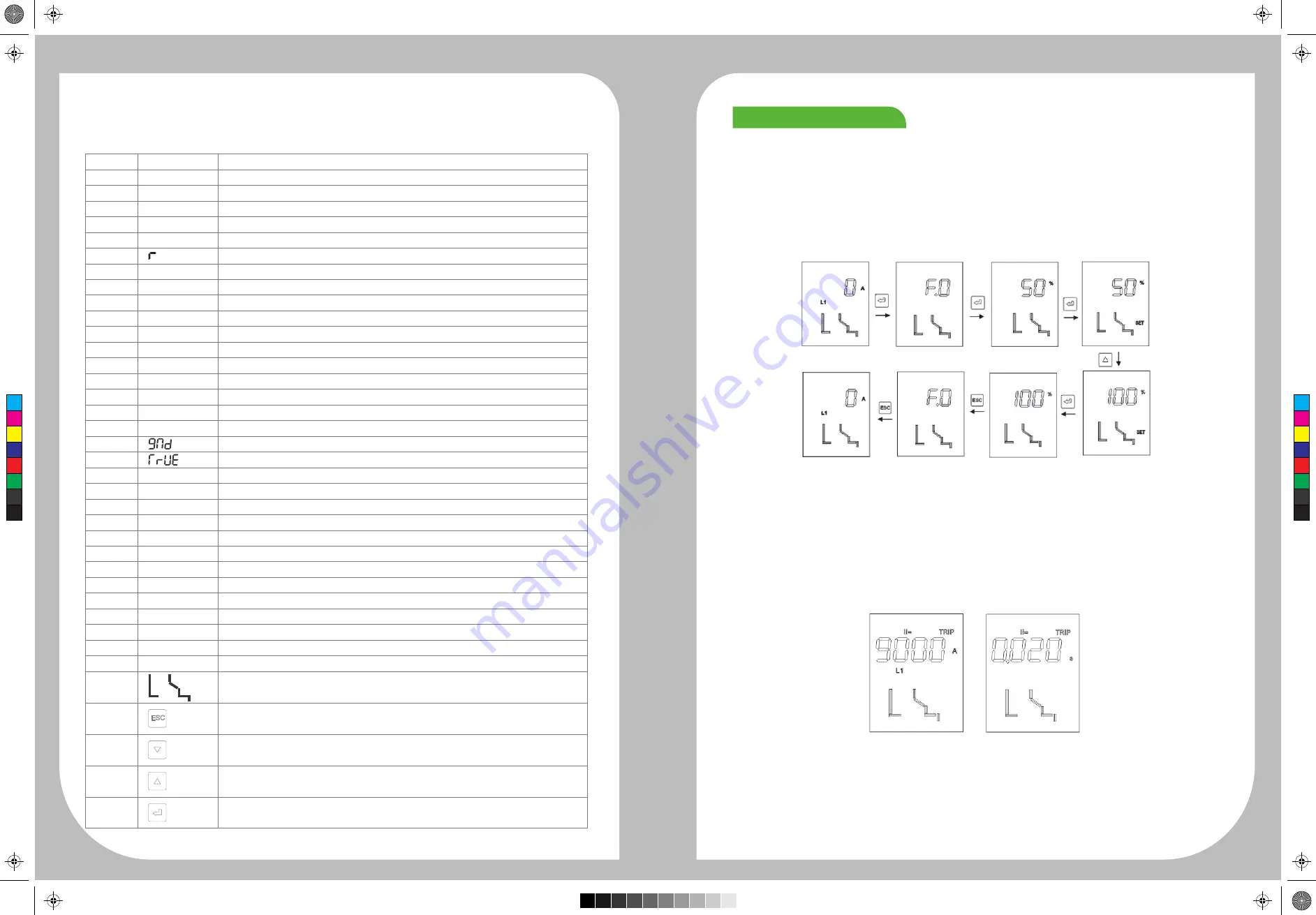
Example of parameter setting:
Press “OK” in the default interface to enter the menu setting interface F0 of the controller. Press “OK”
to enter the parameter setting or view interface. Continue to press “OK” to enable the parameter setting interface, “SET” symbol will
appear in the lower right corner of the interface, where the parameters can be set by pressing “UP” and “DOWN” in this interface.
After setting the parameters, press “OK” to save them and “ESC” to the default interface.
Main function menus and settings of the M type control unit :
F0: Neutral protection setting: 50%, 100%, OFF.
F1: Current unbalance setting: ON (OFF), current unbalance rate setting, delay time setting.
F2: Thermal memory setting: ON (OFF), thermal memory recovery time setting.
F3: Test function setting: LSI protection test, ground-fault protection test.
F4: Communication setting: communication address (1-247), baud rate (9600, 19200).
F5: Trip record view: Take the instantaneous trip for example. Press “OK” in the default interface, select the F5 menu by pressing “UP”
and “DOWN” , and then press “OK” to enter the trip record view interface. Select the serial number (e.g. 01) of record, and press
“OK” . The instantaneous trip current interface will appear. The trip time interface can be viewed by pressing “UP” and “DOWN” .
F6: Alarm records include the magnetic break alarm, CT break alarm and overload alarm. E1 represents the magnetic break, and
E2 represents CT break alarm.E3 represents action reject.
F7: Position change records include opening, closing and trip event records.
F8: View menu for LSIG protection setting, used to view the existing knob settings.
Note: Long-time delay OFF setting: Set the Tr to 30S and enter the menu F8. Adjust Tr to the OFF status to disable long-time
delay.
Overview of Functions
C
M
Y
CM
MY
CY
CMY
K


