background image

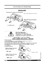
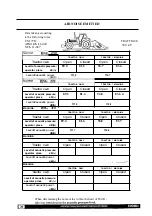
BELT TENSION

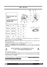
A

B'

I

Load

Arrow

( F

Loosen bolts 

(

A,

no.

4

)

and

(

B,

no.

1

)

which fasten transmission to shredder frame. 

Loosen adjusting screw counternuts 

(

H

and

D

).

Turn

adjusting screw 

(

E

)

clockwise, and turn screw

(

G

),

anticlockwise, up to get the tension 

desired (See the table). 

That operation allows transmission axis 

(

PR

)

to be parallel to rotor axis. 

Tighten bolts

(

A

and

B

)

and counternuts

(

D

and

H

).

In

order to check parallelism between transmission 

axis

and rotor

axis,

follow the indications 

listed below: 

IF THE MACHINE

IS COUPLED

TO

THE TRACTOR,

THE

CARDAN TRANSMISSION

Dismount the belt safety guard. 
Put a scale on the edges of the rotor pulley and rotate it until it touches

the

edges of the other pulley.

Both pulley edges shall touch the scale;otherwise, screw or unscrew adjustingscrew

(G

)

accordingly,

after loosening screws

(

A

and

B

).

Shredders model

BNG are equipped with belts type SPBX

:

tension

of

such belts must be

restored within the first

3

working hours.

Afterwards, check belt tension periodically.

If rotor rotation speed decreases and belt tension can not

be

restored correctly, 

change belts.

I

C

E

Summary of Contents for BNG 230

Page 1: ...4 COSTRUZlONl MECCANICHE PERVGRICOUURA Trince Broyeur Shredder Mulchgerat...

Page 2: ...NG multivalent shredders have been designed for treating beet leaves potato leaves maize stalks grass etc Machine tools blades or rams must NEVER touch the ground The correct use of the machine includ...

Page 3: ...Workingheightadjustment How to displacethe drawbarand adjustmentto P T O speed Parkingposition Airnoiseemitted Maintenanceandlubrication Belttension General instructionsforbladeorram replacement Acce...

Page 4: ...u a celles de la directive est conforme aux dispositions des normes EN294 E N 3 4 9 nationales et a u x dispositions techniques suivantes est egalment c o n f o r m e a u x normes I u v v V V 3 V 3 4...

Page 5: ...g Yes Yes Yes No Rear wheels 2 2 2 No Rear roller Yes Yes Yes Yes Open machine guards Yes Yes Yes No Product spraeder flaps N 6 8 8 No Restings skids Yes No No Yes Trasversal SI 2 No Yes 8 No Max tras...

Page 6: ...chine accordingto the pictures below Decals have been designed for your safety and for other people s safety The machine s owner or the person in charge must be sure the operator has read the Instruct...

Page 7: ...THE KEY OFF BEFORE SERVICINGOR ADJUSTING THE MACHINE 0012215 I GREASE EVERY 4 WORKING HOURS 7 1 0011989 I GREASE EVERY 50 WORKING HOURS READ THE INSTRUCTION I MACHINE 4 DANGER THROWN OBJECTS STAND OF...

Page 8: ...k oads o transmission components ung er A n ricbsorgane Lan anlaufcn ATTENZIONE Avviarc er cvitarc Idannorc N Icsfuortos a de tranrmision CUI DADO Arrancar ament para cv i tar 13 THE MACHINE FROM THE...

Page 9: ...PERVISED DO NOTWEAR CLOTHINGTHAT MAY CATCH UP INTHE MOVING PARTS DO NOT TRANSPORT PERSONSAND ANIMALS ON THE MACHINE MAKE SURETHE TRANSMISSIONSHAFT IS MARKED BEFOREASSEMBLING THE SHAFT CHECKTHAT GUARDS...

Page 10: ...THE WHEELS ARMS SO AS TO PREVENT THEIR ROTATION If mounted USE HOISTING ECQUIPMENT ACCORDING TO THE RULES IN FORCE AND RAIGHT FOR THE MACHINE WEIGHT WARNING BE AS ACCESSOIRES AFFECT MACHINE BALANCE NE...

Page 11: ...WING OF BODIES I SAFETY RANGE MACHINE IN CLOSED MODEL CULARLY CAREFUL WHEN YOU WORK ON RISES OR THE UNEVEN GROUND CAN MAKETHEGUARDSTEMPORARILY 8 INEFFICIENT AND ALLOW THE PROJECTION OF STONES OR FRAGM...

Page 12: ...blades and rams with consequentprojection of fragmentsat highspeed L L MACHINE WMU VKR INITIAL THE H O L E 1 MAXIMUM DIAMETER 0 71 1 07 INITIAL HAMMER I from the original The length L of the blade or...

Page 13: ...ake use of the pair of holes F on the lateral sides On the roller support select the proper holes so as to get up the machine from the ground at the height required See page 17 Mount guards SL on the...

Page 14: ...er follow theundulations in caseof long ways with the double freewheel gearbox unit The rotation way of machine is right any is Getup the machinefromthe ground and adjustcuttingheight working height a...

Page 15: ...tal pipes remain overlapped at least of 1 3 of the length L If the overlappingis smaller there is too much differencebetween the minimumand maximum position of the transmission If this occurs it is ne...

Page 16: ...AS and fit them into the holes corresponding to those selected on the other side Screw and tighten all bolds NG 230 270 270B 310 BNG 270 F AS WHEELS VERSION LIFT MACHINE FROM THEGROUND Loosen bolt C...

Page 17: ...e BNG 270 B e BNG 310 Remove the guard Loosen the fastening screws of the transmission secpag 22 remove the belts Loosen the bolts of the connection remove pulley Reassemble the pulley change their po...

Page 18: ...LAT GROUND TO PERFORM THE FOLLOWING OPERATIONS Lower foot P Lower the elevator until the machine rests on the ground Disconnect propeller shaft and hitch it to the suitable hook G so as to avoid Extra...

Page 19: ...NG 310 Levelo f acoustic power 111 0 115 2 TRACTOR ONLY TRACTOR MACHINE Tractor cab Open Closed Open Closed Levell of acoustic pressure 89 4 81 6 94 8 83 7 operator place dB A dB A Level o f acoustic...

Page 20: ...l BNG 230 270 310 I Every day check oil level BNG 270F 270B Rest the machine horizontally and unscrew the main plug located on the right Make sure the unit is equipped with air drain plug T side oil s...

Page 21: ...rotoraxis followtheindications listed below IF THE MACHINE IS COUPLED T O THE TRACTOR THE CARDAN TRANSMISSION Dismountthe belt safetyguard Put a scaleon the edgesof the rotor pulley and rotate it unti...

Page 22: ...ularly selectingcouplesof sameweight Thosecouplesshallbe mountedonrotorin diametricallyopposedpositions REPLACETHE SELF LOCKINGNUTS IN ANY CASE TightenM 16nuts with a 100Nm torquewrench setting Tighte...

Page 23: ...theupperrow of fasteningbolts by drillingthe sheet if necessary holes 10mm STOPTRACTOR ENGINE DISCONNECT TRACTOR P T O TAKE THE KEY OFFTHE DASHBOARD MAKE SURE ALL MOVING PARTS ARE IDLE FRAME METAL SH...

Page 24: ...ularly selectingcouples of sameweight Thosecouplesshallbe mountedonrotorindiametricallyopposedpositions REPLACE THE SELF LOCKINGNUTS IN ANY CASE TightenM 16nuts with a 100Nm torque wrench setting Tigh...

Page 25: ...MACHINE BNG 230 BNG 270 BNG 310 EXAMPLE OF APPLICATION OF REFLECTOR PANELS APPROVED BY THE HIGHWAY CODE FOR EUROPE IN CASE OF ROAD HAULAGE OF THE MACHINE YOU MUST FIT THE WARNINGS SIGNS REQUIRED AND...

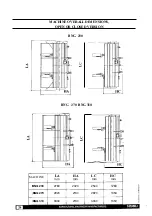
Page 26: ...MACHINE OVERALL DIMENSIONS OPEN OR CLOSED VERSION BNG 230 BNG 270 BNG 310 A LA HA LC HC mm mm mm mm MACHINE BNG 230 2780 2020 2540 1280 BNG 270 2920 2130 2920 1350 BNG 310 3330 2130 3330 1350 I...

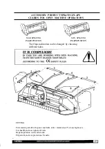
Page 27: ...IN SPRAYNG FLAPS POSITION The flaps inclination can be changed by choosing different holes FITTING Firts mount parts 2 with spacer and bolts after lateral sheet 7 do not tight nuts Fit sheet 8 and now...

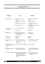
Page 28: ...units and seals A Belt tension really poor Adjust belt tension B Worn out belts Replacebelts A Belt tension not correct Checktension B Transmission axis and rotor Checkalignment axisnot aligned A Lac...

Page 29: ...hine is not used according to the IntendedUse specified in the user s manual Machine guards are removed Guards shall never be removed be periodically checked and if Safety instructionslisted in the us...

Page 30: ...nome che conta I DA BY PAR DURCH 40062 MOLINELLA BO ITALY Via Circonvallazione Sud 46 TEL 051 88 14 44 45 TELEFAX 051 88 27 03...

Reviews: