Use and Maintenance Manual model “H14 V SHAPE”
19
ENGLISH
ENGLISH
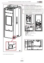
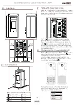
6.3 DIMENSIONS
TUTTI GLI SVILUPPI FORNITI IN FORMATO DXF SONO
TEORICI
. IL PARTICOLARE REALIZZATO DEVE ESSERE CONFORME AL DISEGNO 2D/3D
ALL FLAT PATTERNS PROVIDED IN DXF FORMAT ARE
THEORETICAL
. THE PIECE MUST BE IN COMPLIANCE WITH THE 2D/3D DRAWING
540
1200
575
80
243
336
60
166,5
50
40
60
162
115
141
3/4 MANDATA IMPIANTO
3/4 RITORNO IMPIANTO
1/2 CONNESSIONE
CARICAMENTO
CONNESSIONE
SCARICO
Revisioni
Area
Rev.
Descrizione
Data
Approvata
1
RILASCIO PROGETTO
17/06/2019
R.A.
A
A
B
B
C
C
D
D
E
E
F
F
8
8
7
7
6
6
5
5
4
4
3
3
2
2
1
1
T
-
-
MATRICE (MATRIX)
(SUPPLIER CODE)
ASSIEME MODELLO
SHAPE - 14
CODICE FORNITORE
-
1
N0026-TPHV-EU
-
E.B.
R.A.
17/06/2019
-
-
(DENOMINATION)
Proprietà della Società NOBIS
S.r.l.
Senza autorizzazione scritta della
stessa, il presente disegno non potrà essere utilizzato per la costruzione
dell’oggetto rappresentato né venire comunicato a terzi o riprodotto. La
Società proprietaria tutela i propri diritti a rigore di legge.
All proprietary rights reserved by NOBIS
S.r.l.
This drawing shall not be
reproduced or in any way utilized for the manufacture of the component of
unit herein illustrated and must not be released to other parties without
written consent. Any infringement will be legally pursued.
A3
1:10
DENOMINAZIONE
MATERIALE
DATA
CONTR.
PESO Kg.
TRATTAMENTO SUPERFICIALE (SURFACE TREATMENT)
DISEGNATORE
SCALA (SCALE)
FORMATO (FORMAT)
STATO
(STATUS)
REVISIONE
(REVISION)
TOLLERANZE GENERALI SECONDO LA CLASSE UNI EN 22768-mK
GENERAL TOLERANCES AS PER UNI EN 22768-mK
NOBIS S.r.l.
N. DISEGNO
(MATERIAL)
(DESIGNER)
(DATE)
(DRWG NR.)
(CHECKED)
(WEIGHT)
Via Palazzolo,11 25037
Pontoglio - BS - Italy
P.iva e Cod. Fisc. 04222670160
S
MATERIA PRIMA (RAW MATERIAL)
336
115
60
Ø80
243
162
Ø 60 air
inlet
Ø 80 smoke
discharge
6.4 SAFE DISTANCES
Distanza minima da materiali infiammabili
R Right hand side
150 mm
L Left hand side
150 mm
P Rear
100 mm
F Front
800 mm
L
P
F
R
Floor saving platform
7
PRODUCT CONFIGURATION
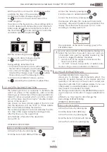
Once all the installation, covering assembly (where
present as a kit) and electrical connection are in
place, with utmost attention, access the rear part of
the product to power it.
The “I/O” switch in the figure above must be
positioned on “I”. In the event of a power failure,
check the condition of the fuse placed under the
switch (4A fuse
EU configuration
). During periods of
non-use, you are advised to disconnect the cable
powering the appliance, and also the batteries from
the handheld device.
A
7.1 CONFIGURATION OF HANDHELD DEVICE
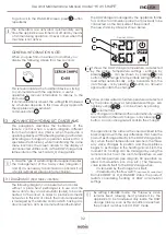
Remove the protective cover of the batteries on the
rear of the remote control, as in the figure , and
insert 3 batteries (type AAA 1.5V)
in the handheld device compartment, paying
attention to polarity. Close the protective cover of
the batteries as in the figure
B
.
A
B
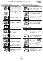
The handheld device, after a first short screen
with the manufacturer’s logo, lists a series of
languages available on the menu.
EMERGENCY REMOTE BOARD
B
A
B
A


