background image

Use and Maintenance Manual model “H14 V SHAPE”


ENGLISH

3.3 CHIMNEY FLUE

When installing the chimney flue, the following provi

-

sions must be applied.

• comply with the product standard EN 1856-1;

• 

it must be installed using materials suitable to  

   guarantee resistance to normal mechanical and 

   chemical stress, and have a correct insulation, to 

   avoid the formation of condensate, therefore it    

   must be hermetically insulated;

• 

have a mainly vertical state and   

   not be choked along its length;

• 

be correctly spaced using 

   air cavities and insulated from flammable 

   materials,

• 

the changes in direction must be 

   at most 2 and with an angle not exceeding 45°;

• the chimney flue inside the home must 

   however be insulated and can be inserted in  

   a cavity provided it complies with the relevant 

   piping standards;

• 

the smoke channel should be connected to the 

chimney flue using a “T” joint with an inspectionable 

collection chamber for collection of fuel residue 

and, in particular, for  condensate collection.

It is not possible to connect the appliance to a 

chimney flue shared with other combustion appli

-

ances or in the presence of hood exhausts.

It is forbidden to use direct wall discharge or 

towards closed spaces or any other form of dis-

charge not planned by legislation in force in the 

country of installation (In Italy, only roof discharge is 

permitted)

3.4 CHIMNEY POT

The standard UNI 10683 states the stack must meet 

the following characteristics:

• 

the smoke outlet section must be at least 

   double the inner section of the chimney;

• 

shaped to prevent 

   water or snow penetration;

• 

be built in such a way that wind 

   cannot affect the smoke outlet 

   (wind-proof cap);

• 

the opening measurement, which is measured 

between the lower coverage protective layer 

   and the lower point of the 

   smoke outlet section into the atmosphere, must be  

   outside the back draught area;

• 

Be built far from antennas or 

   satellite dishes and must never be used as a 

   support.

You are advised to check the safe distances which 

must be complied with in the presence of 

combustible materials and the type of insulating 

material to use (data available directly on the 

chimney flue plate)

3.5 HERMETIC PRODUCT INSTALLATION

In the event of installation of a hermetic product, 

you can execute one of the following types of con-

nection with the piping:

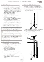
• smoke discharge (1) and recovery of oxidising air 

   directly from outside (2) 

2

1

1

2

2

1

• smoke discharge (1) and oxidising air channelling 

(2) taking advantage of its coaxial discharge 

   to expel the smoke and pick 

   the air; therefore, installation is not necessary 

   of a grate to recirculate the air    

   inside the premises where the 

   the product.

Summary of Contents for H14 V SHAPE

Page 1: ...EN Installation use and maintenance manual H14 V SHAPE...

Page 2: ...appropriate place having carefully consulted it Improper installation maintenance not carried out correctly and improper use of the product relieve the manufacturer of any liability towards people or...

Page 3: ...8 Description of remote controls 21 8 1 Description of receiver 21 8 2 Description of handheld device keys 21 8 3 Description of handheld device display 22 8 4 Flat battery signalling 22 8 5 Concise i...

Page 4: ...ty and maintenance of safety devices do not remove or bypass this devices 1 3 IMPROPER USE The product must be intended for the use for which it was expressly designed for any other use the manu factu...

Page 5: ...on conforming installation with that specified by the manufacturer refer to the installation and use manual supplied with the appliance further damage caused by wrong intervention by the user in an at...

Page 6: ...ng it less comfortable and reducing the overall efficiency of the system Hermetic prod ucts can also be installed in the presence of forced ventilation or in premises which can go into negative pressu...

Page 7: ...ms garage etc and must have a net useful section equal or higher than 80 cm2 pellet burning stoves and thermostoves EN 14785 and 100 cm2 for boilers EN 303 5 The air intake is not necessary for instal...

Page 8: ...rm of dis charge not planned by legislation in force in the country of installation In Italy only roof discharge is permitted 3 4 CHIMNEY POT The standard UNI 10683 states the stack must meet the foll...

Page 9: ...parts such as wood etc In both cases insert adequate insulation 5 be tween the chimney flue and the attic You are advised to check and comply with the plate data of the chimney flue in particular the...

Page 10: ...ician NOBIS SRL cannot be held in any way liable in the event of non compliance with the installation and start up standards of its products 3 8 PRODUCT UNPACKING Packaging is composed of boxes in rec...

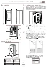
Page 11: ...ide panel from the packaging and insert the hooks placed in the lower part of the same in the slits placed on the base of the product Bring the panel to the vertical position and fasten the upper part...

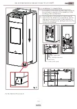
Page 12: ...ll the steps to perform the hydraulic connection of the appliance to the dwelling system are illustrated The connection of the product to the hydraulic system must be carried out exclusively by specia...

Page 13: ...r civil use before installing the appliance is paramount EXPANSION VESSEL The product is equipped with an expansion vessel to compensate for the increase in water pressure inside the boiler in case of...

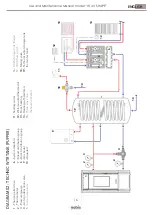
Page 14: ...a pavimento Riscaldamento a termosifoni Valvola a tre vie Risc Sani Accumulo ACS Bollitore Flussostato ACS Valvola miscelatrice Accumulo acqua tecnica Puffer 11 12 13 14 15 16 17 18 19 8 DIAGRAM 00 D...

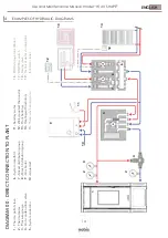
Page 15: ...re vie Risc Sani Accumulo ACS Bollitore Flussostato ACS Valvola miscelatrice Accumulo acqua tecnica Puffer 11 12 13 14 15 16 17 18 19 1 2 3 4 5 6 7 2 9 11 12 12 13 14 10 8 15 16 17 18 DIAGRAM 01 DIREC...

Page 16: ...a tre vie Risc Sani Accumulo ACS Bollitore Flussostato ACS Valvola miscelatrice Accumulo acqua tecnica Puffer 11 12 13 14 15 16 17 18 19 1 2 3 4 6 7 2 9 11 12 12 13 14 10 8 18 10 19 DIAGRAM 02 TECHNIC...

Page 17: ...parete Riscaldamento a pavimento Riscaldamento a termosifoni Valvola a tre vie Risc Sani Accumulo ACS Bollitore Flussostato ACS Valvola miscelatrice Accumulo acqua tecnica Puffer 6 7 8 15 16 17 DIAGR...

Page 18: ...ANCE The maintenance operations excluding routine cleaning explained in the relevant paragraph must be carried out by authorised technical staff Remember before carrying out any maintenance operation...

Page 19: ...E TREATMENT DISEGNATORE SCALA SCALE FORMATO FORMAT STATO STATUS REVISIONE REVISION TOLLERANZE GENERALI SECONDO LA CLASSE UNI EN 22768 mK GENERAL TOLERANCES AS PER UNI EN 22768 mK NOBIS S r l N DISEGNO...

Page 20: ...ded by inserting pellets from the upper part of the product opening the door Ensure the content of the bag of pellets does not fall around the edges of the tank paying particular attention to centring...

Page 21: ...y re mote board placed at the back of it which allows basic management of the functions in the event the handheld device is faulty or not working properly 1 Serial connection use by authorised staff O...

Page 22: ...nal will confirm the change OK From STAND BY mode pressing allows to obtain an overview of the actual and active device status as shown in the following figure 8 4 FLAT BATTERIES SIGNAL If batteries a...

Page 23: ...tying ACTIVE COMFORT CLIMA RESTART FROM COMFORT CLIMA FINAL CLEANING OFF ALERT see specific paragraph FLAME OVERHEATING PELLET OVERLOAD 8 5 CONCISE ICONS DIAGRAM 1 2 4 3 MEANING H2 O STANDBY FAULT PRE...

Page 24: ...eference standard thermostat OPERATING PROCEDURE MENU USER SETTINGS SETTINGS PROBE CALIBRATION Access menu by pressing Scroll down entries to select USER SETTINGS using Access menu by pressing OK OK B...

Page 25: ...signalling causes switching off of the prod uct as well as resetting of any alarms For models with an automatic cleaner during the switch on phase the product activates a brazier cleaning phase befor...

Page 26: ...ermines the temperature gradient according to which the appliance must restart STATUS SCREEN To see the shutting down of the appliance while in COMFORT CLIMA mode screen must be displayed To see that...

Page 27: ...d so as to turn it off once the temperature in the room where the product is in stalled has been reached by means of the remote control and using only an external thermostat for the device environment...

Page 28: ...LEAN ING status before starting the function The number expressed in seconds indicates the rota tion time of the auger during the loading phase After this time is up the auger stops automatically afte...

Page 29: ...m by pressing the key and pass to edit extraction OK Edit the extraction setting keys The values vary from 5 reduction in extraction in to 5 increase in extraction in Confirm by pressing the key and e...

Page 30: ...ing system in the presence of DHW storage tank with SUMMER settings OPERATING PROCEDURE MENU USER SETTINGS SETTINGS SEASON Access menu by pressing Scroll down entries to select USER SETTINGS using Acc...

Page 31: ...ND BY screen use the key repeating the operation multiple times 12 10 ANTICONDENSATION exhaust fumes temperature This function ensures that the temperature of exhaust gases remains higher than condens...

Page 32: ...ge or by pressing button An acoustic signal will confirm the change OK The operation is the same as the one described in the basic diagram with the only difference that here the product exchanges dire...

Page 33: ...heating by means of a con tact or immersion probe not provided always to be connected on the back side of the product The new stand by screen is shown below STAND BY SCREEN 1 2 2 It shows the technica...

Page 34: ...LEANING OFF WAITING FOR FLAME FLAME PHASE RESTART PHASE DESCRIPTION Room temperature set on MAN mode In this case the appliance will operate only when firebox power is set it NEVER switches to eco mod...

Page 35: ...on tact an authorized technician to solve the problem Anomaly to the upstram probe mo nitoring the water temperature in the technical water storage tank hot water tank please contact an authorized tec...

Page 36: ...ALARM CODE REASON 10 PELLET LOADING AUGER POWER SUPPLY DEFECT No power supply or power supplied by elec tronic control unit not correct SOLUTION If the problem persists contact the Support Service AL...

Page 37: ...ION If the problem persists please contact the Assistance Service ALARM CODE SOLUTION 27 PUMP FAILURE The pump does not worlk properly or cannot start SOLUTION If the problem persists please contact t...

Page 38: ...detergents or diluents causes damage to the surface of the product 19 1 CLEANING THE FIREPLACE Open the fire door using the specific tool and vacuum the slide bringing the ash to the brazier dismantle...

Page 39: ...h an abrasive function avoiding use of products with additives that could over time wear the seals glass and paint Do not switch on the appliance if the glass is damaged Contact the support service to...

Page 40: ...hich are indispensable for correct appliance operation PARTS FREQUENCY TIME Ash pan approx time 7 DD Glass 2 3 DD Extraction pipe 1 SE Door seal ash pan 1 SE Tube bundle scraper where present 7 DD Chi...

Page 41: ...ON MANUAL RESET THERMAL SWITCH CONTACT DOOR ASH PAN 1 PELLET TANK 2 220V SOCKET WITH ON OFF SWITCH AND FUSE SAFETY VACUUM SWITCH VENTILATION FRONT PC CONNECTION technical support only USB CONNECTION t...

Page 42: ...Use and Maintenance Manual model H14 V SHAPE 42 ENGLISH DATE NOTE...

Page 43: ...Use and Maintenance Manual model H14 V SHAPE 43 ENGLISH DATE NOTE...

Page 44: ...N 11 25037 Pontoglio BS www nobisfire it Cod 110 002 0014N_S1 Nobis Srl cannot be held in any way liable for any errors in this manual and considers itself free to change the features of its products...

Reviews: