background image


17 


A.  SPECIFICATIONS 

Input Volt: 150 – 260 V, AC 50 – 60 Hz 
Output Volt: 145 V ±0.3 
Output Current: 5 – 6 Amp 
Applicable Ambient Temperature: –15 - +65

℃ 


B.  OPERATION 

1. Insert the plug of the power cable into the socket of the power line. 

1)  Power Indicator lights (red) 
2)  Charging Indicator turns on red, indicating the battery is in charging. 

2. When Charging Indicator turns from red to green, the battery is nearly full. Charging 

can continue in the Floating Stage. 

3. When the battery is fully charged, disconnect the Power Cable from the Power Line. 

+12 V Output Cable has power. 


C.  WARNING 

1. During charging the truck can’t be lifted electrically! 
2. Do not use the truck in wet areas or conditions. 


Table 3: Charging LED 

LED- signal 

Function 

Red 

Battery discharged 

Green 

Fully charged 


When charging is finished, disconnect the connector from the socket and place it in the designated pocket. 

e. 

Charging with external charger (only ACX 10E, optional) 

The fully automatic external charger uses pulse charging. It can effectively alleviate the phenomenon of 
cell  polarization,  extend  the  service  life  of  battery  and  has  fast  charge,  slow  charge  and  float  charge 
functions.  It  automatically  selects  the  charging  state  according  to  the  detected  battery  voltage  and 
converts into floating charge state when the battery is fully charged. 

Disconnect the Emergency plug and connect the charger plug with the battery sided connector. Connect 
the power cord of the charger to the main power supply. After switching on the charger, the charging starts 
automatically. 
For further information read the instruction handbook of the external charger. 

8. REGULAR MAINTENANCE   


  Only qualified and trained personnel are allowed to do service on this truck. 

  Before servicing the truck, remove the load and lower the forks to the lowest position. 

  Completely  immobilize  the  truck  before  working  on  components  that  might  pinch 

fingers or hands if movement were allowed.   

Summary of Contents for ACX 10E

Page 1: ...ese operating instructions NOTE Please check the designation of your present type at the last page of this document as well as on the ID plate Keep for future reference OPERATING INSTRUCTION HANDBOOK...

Page 2: ...1...

Page 3: ...rsion assumed the truck is used according to the described purpose ATTENTION Environmentally hazardous waste such as batteries oil and electronics will have a negative effect on the environment or hea...

Page 4: ...3...

Page 5: ...ATING INSTRUCTIONS 14 a Parking 14 b Lifting 14 c Lowering 14 d Moving 14 e Quick Lift ACX 10M 15 f Malfunctions 15 7 BATTERY CHARGING AND REPLACEMENT ACX 10E 15 a Replacement 15 b Battery indicator 1...

Page 6: ...5...

Page 7: ...to be used on substantially firm smooth level and prepared surfaces Driving with the load on slopes is not allowed The load must be placed approximately on the longitudinal centre plane of the truck a...

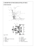
Page 8: ...s 1 Chassis 2 Tiller arm 3 Hydraulic cylinder and manual pump 4 Steering wheel 5 Scissors 6 Control lever 7 Lifting button 8 Key switch 9 Hydraulic power pack 10 Emergency plug 11 Battery inside 12 On...

Page 9: ...front rear x driven 2 2 2 2 3 6 Tread front b10 mm 155 155 3 7 Tread rear b11 mm 440 440 Dimensions 4 4 Lift standard mast h3 mm 715 715 4 5 Height mast extended h4 mm 1660 1660 4 9 Height of tiller i...

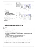
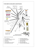
Page 10: ...ACX 10E E Warning decal Do not step under or on the forks F Never reach through G Load diagram H Identification plate The safety and warning labels should be placed according to figure 3 The advices...

Page 11: ...surface the truck may become uncontrollable and create danger Lift or carry people People could fall down and suffer severe injury Use truck with unstable unbalanced loosely stacked load Use the truck...

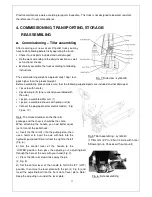
Page 12: ...assembled tiller arm 1 1 pc pre assembled chassis with pump unit 6 Connect the plug optional for electric model Fig 1 pos 10 Note The marked number on the tiller arm package and the chassis should be...

Page 13: ...the Slow Lift position turn the adjusting nut clockwise until the Slow Lift position works properly If the forks do not lift quickly while the control handle is in the Quick Lift position turn the adj...

Page 14: ...ty so that there will be no flattening after storage Reassemble the tiller in the opposite direction of the assembling 5 DAILY INSPECTION This chapter describes pre shift checks before putting the tru...

Page 15: ...k is equipped with 2 supports At a height of approx 400 mm the supports automatically set on the floor Once the supports are in place further movement is not allowed respective not possible For the el...

Page 16: ...ed Smoking is prohibited and the area must be ventilated Park the truck securely before starting charging or installing changing the batteries Before finishing the maintenance work make sure that all...

Page 17: ...oom where you are charging must be ventilated The exactly charge status can be only checked from the dischrge indicator To control the status the charging must be interrupted and the truck must be sta...

Page 18: ...ated pocket e Charging with external charger only ACX 10E optional The fully automatic external charger uses pulse charging It can effectively alleviate the phenomenon of cell polarization extend the...

Page 19: ...ed with long life grease at the factory Long life grease should be applied to the lubrication points at monthly intervals or after each time the truck is cleaned Clean off dirt and debris EVERY THREE...

Page 20: ...mp does not operate Defective fuse FU1 or FU2 Loose or unconnected plug Defect motor Replace the fuses Reconnect Replace motor 2 The high lift pallet truck does not lift the load although the pump is...

Page 21: ...too slowly Temperature too low the hydraulic system oil is too thick Operate the truck in warmer locations 6 Fork does not raise till upper position Insufficient oil in the tank Battery discharged Ref...

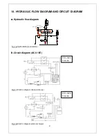
Page 22: ...GRAM a Hydraulic flow diagram b Circuit diagram ACX 10E Fig 18 Electric diagram external charger Fig 17 Electric diagram onboard charger M L O W E R IN G N E U T R A L L IF T IN G Fig 16 Hydraulicdiag...

Page 23: ...ASME B56 1 concerning the operator In this standard it is defined that the safe operation is the responsibility of the operator ASME B56 1 2003 Part II section 5 1 1 You and others can be seriously in...

Page 24: ...cation plate ID Plate I Truck identification plate number J Sign warning electrical devices K Sign danger battery L Sign caution charger M Sign warning battery size N Combined emergency battery plug D...

Page 25: ...ACX 10E Sign read and follow this instruction B Sign operating instruction C ACX 10M ACX 10E Sign danger battery K only ACX 10E Sign caution charger L only ACX 10E Sign warning battery size M only ACX...

Page 26: ...25...

Page 27: ...ttive Europee 2006 42 EC Direttiva Macchine e 2004 108 EEC Compatibilit elettromagnetica EMV comprese le relative modifiche come pure il rispettivo decreto legislativo per la conversione delle diretti...

Page 28: ...sani s tem potrjujemo da posami no ozna eno dolo eno stroj vozilo odgovarja Evropski direktivi 2006 42 EC Direktiva o strojih in 2004 108 EEC Elektromagnetna skladnost EMV vklju no z njihovimi spremem...

Reviews: