30
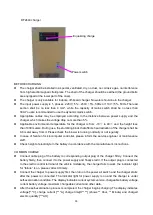
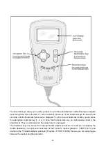
DF2440 charger
Equalizing charge
Power switch
BEFORE CHARGING
The charger shall be installed in a special, ventilated, dry, no dust, no corrosive gas, no interference
from high electromagnetic field place. The shell of the charger should be earthed (the ground bolts
are equipped at the lower part of the case).
The charger is only available for indoors, off-board charger. No water should be in the charger.
The input power supply is 1- phases, 220V
±
5%
~
230V
±
5%, 50Hz or 110V
±
5%, 50Hz.The lead
section shall be no less than 4 mm², while the capacity of mains switch shall be no less than
30A.You are recommended to use the dynamic mains switch.
Appropriate cables may be employed according to the distance between power supply and the
charger, which makes the voltage drop no more than 5%.
Applicable environmental temperature for the charger is from -10
℃
to 40
℃
and the height less
than 1000 meters. During use, the stumbling block that affects heat radiation of the charger shall be
0.6 meter away from it. Please check the blower is running normally or not regularly.
In case of failure of microcomputer controller, please inform the service engineer or maintenance
staff.
Check height of electrolyte in the battery in accordance with the manufacturer’s instructions.
COMMON CHARGE
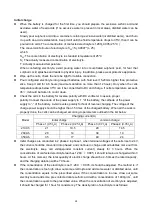
Connect cable plug of the battery to corresponding output plug of the charger firmly. Connect the
battery firstly, then connect it to the power supply and finally start it. If the output plug is connected
to the electric control terminal of the vehicle mistakenly, the charger fails to work, the indicator light
for “failure” is on, please correct it timely.
Connect the charger to power supply first, then turn on the power air switch and the charger starts
after the power is connected. The indicator light for power supply is on and the charger is under
self-examination condition. The display indicates current system version, chargeable battery voltage,
current battery voltage, maximum chargeable current and other data.
After the self-examination process is completed, the charger begins charging. The display indicates
voltage[**.*V], charge current [**.*A], charge time[H**.**] (shows ** Hour, ** Minute) and charged
electric quantity [***AH].
Summary of Contents for CG1646
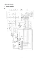
Page 16: ...18 3 ELECTRIC SYSTEM 3 1 ELECTRIC DIAGRAM WIRING DIAGRAM ...
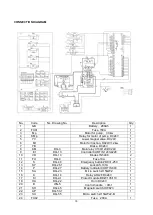
Page 19: ...21 CG1646 Universal Electric Parts List ...
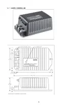
Page 31: ...33 3 7 CURTIS CONTROLLER ...
Page 50: ...52 5 DRIVE WHEEL 5 1 THE DRIVE WHEEL Driving Wheel MR250FR ...
Page 64: ...66 9 2 TROUBLE SHOOT ...
Page 65: ...67 ...

