36
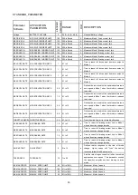
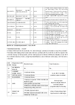
CREEP SPEED
CREEP SPEED LIMIT
0
0% to 25%
%
Defines a minimum speed (duty factor) output from
the controller. The controller output will jump to
this speed when a direction has been selected
THROTTLE TYPE
5
THRTL
DEADBAND
THROTTLE DEADBAND
10
0 to 40
%
Percentage of throttle movement which represents
the neutral deadband
THROTTLE MAX
THROTTLE MAX. OUTPUT
POINT
95
60 to 100
%
Percentage of throttle movement at which full
controller output duty cycle is attained
THROTTLE MAP
THROTTLE MAP
50
20% to 80%
%
Adjusts desired PWM output at 50% throttle to vary
throttle sensitivity at low speeds
FIELD MIN
MINIMUM FIELD CURRENT
LIMIT
5.4
1.6A to Max Field
C/L
A
Minimum allowed current in the field winding. Sets
max vehicle speed
FIELD MAX
MAXIMUM FIELD CURRENT
LIMIT
15
Min Field C/L to
Rated
A
Maximum allowed current in the field winding.
Limits power dissipation in low impedance field
windings.
FLD MAP START
FIELD MAP START
40
25 A to Full Drive
Current
Adjusts the minimum armature current at which the
field current may begin increasing. This parameter
is used to adjust the vehicle's maximum full load
speed.
FIELD MAP
FIELD MAP
50
0% to 100%
Adjusts desired field current at 50% Armature
current. Affects speed characteristic under different
load conditions
CURRENT RATIO
CURRENT RATIO
1
1, 2, 3, 4
Adjusts the rate of current increase as a function of
throttle
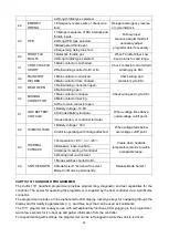
RESTRAINT
RESTRAINT
10
Off (0),Brake (1),
KSI (2)
A
Adjusts the braking strength applied to the motor
when throttle request is decreased or the if the
vehicle is moving when zero throttle is requested
LOAD COMP
LOAD COMPENSATION
5
Off (0), Brk(1), KSI
(2), KSI, Brk & Fwd
only (3)
Adjusts the controller's response to increasing
motor loads at a fixed throttle request
HPD
HIGH PEDAL DISABLE (HPD)
2
Off (0),Brake (1),
KSI (2)
Disables controller if >25% throttle is applied before
the KSI and/or brake inputs.
SRO
STATIC RETURN TO OFF
(SRO)
2
Off (0), Brk(1), KSI
(2), KSI, Brk & Fwd
only (3)
Requires sequencing of KSI and Brake before Fwd
and Rev or KSI and Brake before only Fwd is
selected
SEQUENCING DLY SEQUENCING DELAY
0.2
0 to 3
s
Delay time before HPD and SRO faults are
registered after the brake input is disengaged
MAIN CONT INTR
MAIN CONTACTOR
INTERLOCK
1
On/Off
Turns on main contactor with interlock(ON) or with
KSI (OFF).
MAIN OPEN DLY
MAIN CONTACTOR DROPOUT
DELAY
3
0-40
s
Enables or disables a 40 sec. delay time between
brake switch and main contactor drop out.
CONT DIAG
CONTACTOR DIAGNOSTICS
1
On/Off
When "ON", enables the missing and welded
contactor fault checks on the main contactor only.
AUX TYPE
AUXILIARY DRIVER TYPE
5
Types 0 - 5
A low side driver that can be programmed to drive a
variety of E-M brake options, hourmeter, pump or
brush motor contactor. This driver is short circuit
protected
AUX DELAY
AUXILIARY DRIVER TURN
OFF DELAY
0.6
0-30
s
Programmable time delay between throttle release
to neutral (no direction selected) and Auxiliary
Driver turn off.
EMR REV ENABLE
EMERGENCY REVERSE
ENABLE
1
On/Off
Defines whether the Emergency Reverse function is
active or disabled.
EMR REV C/L
EMERGENCY REVERSE
CURRENT LIMIT
80
50A to Rated
A
Maximum allowed armature current during braking
in emergency reverse
Summary of Contents for CG1646
Page 16: ...18 3 ELECTRIC SYSTEM 3 1 ELECTRIC DIAGRAM WIRING DIAGRAM ...
Page 19: ...21 CG1646 Universal Electric Parts List ...
Page 31: ...33 3 7 CURTIS CONTROLLER ...
Page 50: ...52 5 DRIVE WHEEL 5 1 THE DRIVE WHEEL Driving Wheel MR250FR ...
Page 64: ...66 9 2 TROUBLE SHOOT ...
Page 65: ...67 ...

