37
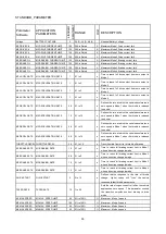
EMR DIR INTR
EMERGENCY REVERSE
DIRECTION INTERLOCK
0
On/Off
Dictates controller response after the emr rev switch
has been activated. When "ON", the controller
becomes active if either the throttle is returned to
neutral or the Interlock switch is cycled. When
"OFF", the Interlock switch must be cycled.
EMR TIME LIMIT
EMERGENCY TIME LIMIT
1
On/Off
Enables / disables EMR to operate for a specific
time
EMR TIMEOUT
EMERGENCY REVERSE
TIMEOUT
2.5
0.1 - 3.0
s
Emergency reverse operates for the specifed time.
VARIABLE BRAKE VARIABLE BRAKING
1
On/Off
Defines whether braking current limit is dependent
upon throttle position or is fixed
ANTI-TIEDOWN
ANTI TIEDOWN
0
On/Off
Prevents vehicle operation in Modes 2 or 4 if the
Modes 2, or 4 are active when the brake is first
released
MODULE ID
MODULE ID
5
0-15
CAN bus module identification address.
RX COB
RX COB
1
0-128
CAN bus transmit communication object. This
defines the value of the identifier type for a PDO
SYSTEM message for transmission.
TX COB
TX COB
1
0-128
CAN bus receive communication object. This
defines the value of the identifier type for a PDO
SYSTEM message for reception.
CAN TMO ENABLE CAN TMO ENABLE
1
On/Off
Enables or disables a CAN bus communications
watchdog. Loss of PDO messages once started
will generate ERROR frames.
NOTE: for “standard parameter”, 1=on, 0=off
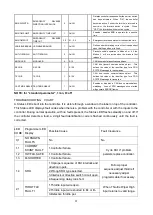
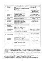
TROUBLESHOOTING CHART
A Status LED is built into the controller. It is visible through a window in the label on top of the controller.
This Status LED displays fault codes when there is a problem with the controller or with the inputs to the
controller. During normal operation, with no faults present, the Status LED flashes steadily on and off. If
the controller detects a fault, a 2-digit fault identification code is flashed continuously until the fault is
corrected.
LED
CODE
Programmer LED
Display
Possible Cause
Fault Clearance
0,1
NO KNOWN
FAULTS
No
No
1,1
CURRENT
SHUNT FAULT
1.Controller failure.
Cycle KSI .If problem
persists,replace controller.
1,2
HW FAIL SAFE
1.Controller failure.
1,3
M-SHORTED
1.Controller failure.
1,4
SRO
1.Improper sequence of KSI,interlock,and
direction inputs.
Follow proper
sequence;adjust throttle if
necessary;adjust
programmable if necessary.
2.Wrong SRO type selected.
3.Interlock or direction switch circuit open.
4.Sequencing delay too short.
2,1
THROTTLE
FAULT 1
1.Throttle input wire open.
When Throttle Wiper High
input returns to valid range.
2.Throttle input wire shorted to B+ or B-.
3.Defective throttle pot.
Summary of Contents for CG1646
Page 16: ...18 3 ELECTRIC SYSTEM 3 1 ELECTRIC DIAGRAM WIRING DIAGRAM ...
Page 19: ...21 CG1646 Universal Electric Parts List ...
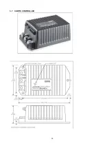
Page 31: ...33 3 7 CURTIS CONTROLLER ...
Page 50: ...52 5 DRIVE WHEEL 5 1 THE DRIVE WHEEL Driving Wheel MR250FR ...
Page 64: ...66 9 2 TROUBLE SHOOT ...
Page 65: ...67 ...

