11
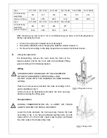
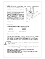
Fig. 9: Residual lift diagram
Make sure, that the load is palletized and stable and that the daily inspection is carried
out. For starting, insert the key and turn it clockwise to the “ON”- position. The key can
be used only used on pedestrian controlled power stacker. Eventually before inserting
the key, the emergency button must be pulled carefully.
Press the horn button (21) to activate the audible warning signal.
a.
Parking
DO NOT PARK THE TRUCK ON INCLINED SURFACES
The truck is equipped with an electromagnetic failsafe stopping and parking brake.
Always lower the forks fully and drive the truck to a safe area. Turn the key anti-
clockwise to the “Off” – position and remove the key.
b.
Residual lift diagram
The residual lift diagram indicates the maximum capacity Q
[kg] for a given load centre c [mm] and the corresponding lift
height H [mm] for the truck with horizontal load.
The white markings on the mast indicate if the specific lifting
limits reached.
For instance with a load centre of gravity distance c of 600 mm
and a maximum lift height H of 3500 mm, the max. capacity
Q is 600 kg.
c.
LiftingDO NOT OVERLOAD THE TRUCK! THE MAXIMUM CAPACITY IS
1000 kg.
LIFT ONLY CAPACITIES ACCORDING TO THE RESIDUAL LIFT
DIAGRAM.
Travel with the lowered forks fully underneath the pallet and press the lifting button (fig.
7, 22) until you reached the desired lifting height.
d.
Lowering
If the forks are in the racking, firstly travel out of the
racking carefully with or without the pallet.
Press the lowering button (fig. 7, 23) carefully.
Lower the load until the forks are clear of the pallet,
then drive the truck carefully out of the load unit.
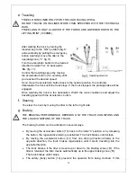
Fig.10: Load facing uphill
Summary of Contents for ECL 10
Page 28: ......
Page 31: ...3 Fig 1 Main components...
Page 36: ...8 Fig 5 Mast Assembly 5 1 Double Mast...
Page 38: ...10 Fig 6 Electronic control board assembly...
Page 41: ...13 Fig 8 Electric parts and components...
Page 53: ...25 Fig 14 Tiller arm assembly...
Page 55: ...27 Fig 15 Economic tiller head...
Page 60: ...32 Fig 18 Sticker for US...
Page 65: ...4 Fig 2 S ticker for US...
Page 67: ...6 Fig 3 Appearance...
Page 74: ...13 Fig 8 Mast assembly 8 1 Two stage mast...
Page 76: ...15 Fig 9 Electronic control board assembly...
Page 79: ...18 Fig 11 Electric parts and components...
Page 88: ...27 Fig 15 Driving system...
Page 91: ...30 Fig 17 T iller arm assembly...
Page 93: ...32 Fig 18 Economic tiller head...


