13
button is activated, the truck decelerates and/ or starts travelling into the backwards
direction (‘Bw.’) for a short distance and stops. Please consider, that this button also
operates, if the truck is not travelling and the tiller is in the operating zone.
h.
Malfunctions
If there are any malfunctions or the truck is inoperative, please stop using the truck and
activate the emergency button (3) by pushing it. If possible, park the truck on a safe
area, turn the key switch (1) anti- clockwise and remove the key.
Inform immediately the manager and, or call your service. If necessary, tow the truck
out of the operating area by using dedicated lifting equipment.
i.
Emergency
In emergencies, push the emergency button (3). All electrical functions will be stopped.
Keep safe distance.
5. BATTERY CHARGING AND REPLACEMENT
Only qualified personnel are allowed to service or charge the batteries. The
instructions of this handbook and from the battery- manufacturer must be
observed.
These batteries are maintenance free; re- filling is prohibited.
Recycling of batteries undergoes national regulations. Please follow these
regulations.
By handling batteries, open fire is prohibited, gases could cause explosion!
In the area of battery charging neither burning materials nor burning liquids are
allowed. Smoking is prohibited and the area must be ventilated.
Park the truck securely before starting charging or installing/changing the batteries
Before finishing the maintenance work, make sure, that all cables are connected
correctly and that there are no disturbing towards other components of the truck.
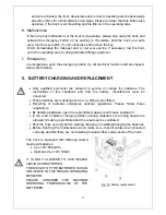
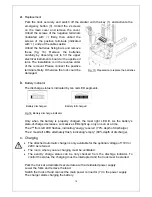
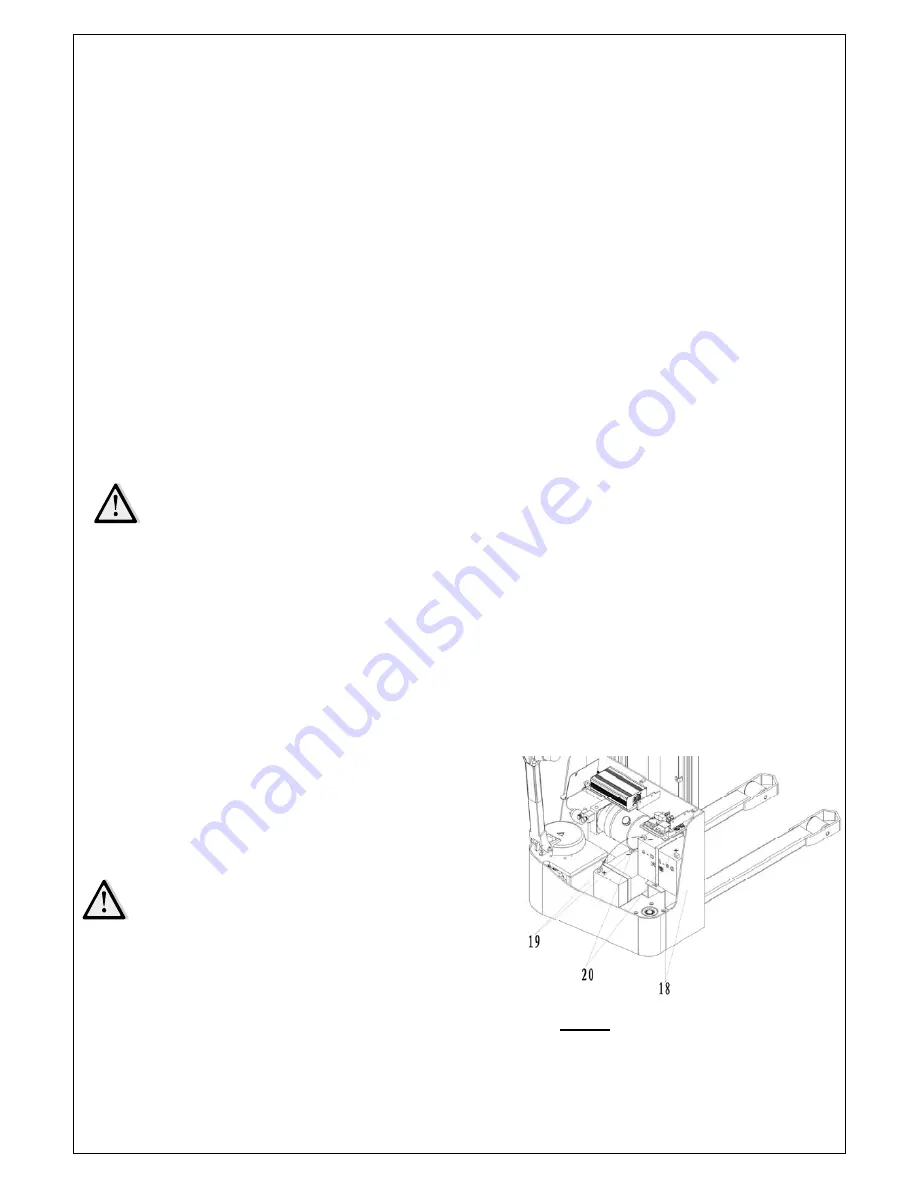
The truck is equipped with following sealed
liquid acid batteries:
2 pc 12V/ 85Ah(C5)
Optional: 2 pc 12V/ 106Ah
IT IS ONLY ALLOWED TO USE SEALED
LIQUID ACID BATTERIES.
THE WEIGHT OF THE BATTERIES HAS AN
INFLUENCE TO THE TRUCKS OPERATING
BEHAVIOR.
PLEASE CONSIDER THE MAXIMUM
OPERATING TEMPERATURE OF THE
BATTERIES.
Fig. 12: battery replacement
Summary of Contents for ECL 10
Page 28: ......
Page 31: ...3 Fig 1 Main components...
Page 36: ...8 Fig 5 Mast Assembly 5 1 Double Mast...
Page 38: ...10 Fig 6 Electronic control board assembly...
Page 41: ...13 Fig 8 Electric parts and components...
Page 53: ...25 Fig 14 Tiller arm assembly...
Page 55: ...27 Fig 15 Economic tiller head...
Page 60: ...32 Fig 18 Sticker for US...
Page 65: ...4 Fig 2 S ticker for US...
Page 67: ...6 Fig 3 Appearance...
Page 74: ...13 Fig 8 Mast assembly 8 1 Two stage mast...
Page 76: ...15 Fig 9 Electronic control board assembly...
Page 79: ...18 Fig 11 Electric parts and components...
Page 88: ...27 Fig 15 Driving system...
Page 91: ...30 Fig 17 T iller arm assembly...
Page 93: ...32 Fig 18 Economic tiller head...


