background image


6


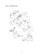
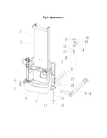
Fig. 3  Appearance 


Summary of Contents for ECL 10

Page 1: ...ic Stacker ECL 10 WARNING Do not use the electric truck before reading and understanding these operating instructions NOTE Please check the designation of your present type at the last page of this do...

Page 2: ...NTION Environmentally hazardous waste such as batteries oil and electronics will have a negative effect on the environment or health if handled incorrectly The waste packages should be sorted and put...

Page 3: ...l lift diagram 11 c Lifting 11 d Lowering 11 e Travelling 12 f Steering 12 g Braking 12 h Malfunctions 13 i Emergency 13 5 BATTERY CHARGING AND REPLACEMENT 13 a Replacement 14 b Battery Indicator 14 c...

Page 4: ...s is not allowed While operating the load must be placed approximately on the longitudinal centre plane of the stacker Lifting or transporting people is forbidden If travelling the load must be lowere...

Page 5: ...arge indicator and charging indicating LED 3 Emergency button 4 Main cover 5 Forks 6 Load wheels 7 Charging cable 8 Drive motor cover 9 Hydraulic cylinder 10 Drive wheel 11 Castors 12 Safety belly but...

Page 6: ...eight kg 510 756 2 2 Axle loading laden front rear kg 580 930 786 970 Weig ht 2 3 Axle loading unladen front rear kg 385 125 530 226 3 1 Tires Polyurethane PU 3 2 Tire size front x w mm 220 70 3 3 Tir...

Page 7: ...76 8 1 Type of drive control DC Speed Control 8 4 sound level at driver s ear acc to EN 12053 dB A 70 Addi tional data 1 Optional 35 100 950 2 Optional 2x12V 106 Ah Other type data 1 2 Manufacturer s...

Page 8: ...the functions Before operating insert the key and turn the switch 1 clockwise To prevent against unauthorized access turn the key anti clockwise and remove it if you not operate this truck The truck...

Page 9: ...ould fall down or the truck could get uncontrollable Keep watching the condition of load Stop operating the truck if load becomes unstable Brake the truck and activate the emergency button 3 by pushin...

Page 10: ...TING Park the truck securely and lash the truck according to the points identified in fig 5 Lift the truck to its destination and place the truck securely before removing the lifting gear Transportati...

Page 11: ...r cracks Check if there is any oil leakage from the cylinder Check the vertical creep of the truck Check the chain and rollers for damages or corrosion Check the smooth movement of the wheels Check th...

Page 12: ...diagram indicates the maximum capacity Q kg for a given load centre c mm and the corresponding lift height H mm for the truck with horizontal load The white markings on the mast indicate if the specif...

Page 13: ...y the truck to the destination Watch the route conditions and adjust the travelling speed with the accelerator button f Steering You steer the truck by moving the tiller to the left or right side g Br...

Page 14: ...arge the batteries The instructions of this handbook and from the battery manufacturer must be observed These batteries are maintenance free re filling is prohibited Recycling of batteries undergoes n...

Page 15: ...ll charged Fig 14 Battery discharge indicator Only when the battery is properly charged the most right LED lit As the battery s state of charge decreases successive LEDs light up only one on at a time...

Page 16: ...ntion by maintain the tiller arm The gas pressure spring is pre loaded by compression Carelessness can cause injury Use approved and from your dealer released original spare parts Please consider that...

Page 17: ...cal system of the drive motor Braking system 27 Check brake performance if necessary replace the brake disc or adjust the air gap Battery 28 Check the battery voltage 29 Clean and grease the terminals...

Page 18: ...ount is 2 5L to 3 0L Waste material like oil used batteries or other must be probably disposed and recycled according to the national regulations and if necessary brought to a recycling company d Chec...

Page 19: ...eck and eventually refill hydraulic oil Load can t be lifted Oil leakage Repair the hoses and or the sealing of the cylinder Oil leakage from air breathing Excessive quantity of oil Reduce oil quantit...

Page 20: ...y travels very slowly The relating tiller cables are disconnected or damaged Check the tiller cables and connections The controller is damaged Replace the controller The stacker starts up suddenly The...

Page 21: ...20 8 WIRING CIRCUIT DIAGRAM a Electrical circuit diagram Fig 19 Electric diagram ECL10 Fuses ECL10 FU1 10 A FU2 0 5 A FU01 60 A FU02 100 A...

Page 22: ...21 b Hydraulic circuit Fig 20 Hydraulic circuit ECL10 Lift cylinder Oil tank Hydraulic power pack motor and pump Pressure valve Throttle valve Lowering valve...

Page 23: ...ection in ASME B56 1 concerning the operator In this standard it is defined that the safe operation is the responsibility of the operator ASME B56 1 2003 Part II section 5 1 1 You and others can be se...

Page 24: ...ign Caution charger I Sign danger battery J Sign warning battery size K Sign warning electrical devices L Sign danger not riding M Sign danger being crushed 3 Combined emergency switch 12 Safety belly...

Page 25: ...truction B Sign warning stay clear stop truck G Sign Caution charger H Sign danger battery I Sign warning battery size J Sign warning electrical devices K Sign danger not riding L Sign danger being cr...

Page 26: ...ione delle direttive in diritto nazionale I sottoscritti sono singolarmente autorizzati alla creazione della documentazione tecnica BG E 2006 42 EG 2004 108 EG CZ EG PROHL EN O SHOD N e podepsan t mto...

Page 27: ...i ter ustrezno pravno uredbo o prevzemu smernic v nacionalno pravo Podpisniki so vsakokrat posamezno poobla eni za izdajanje tehni ne dokumentacije TR AB Uygunluk A klamas mza sahibi ah slar ayr nt la...

Page 28: ......

Page 29: ...1 ECL10 BPT 001 Version 02 2015 ECL10 BPT 006_EN 30150200167 2015 2 Y2015 013 Spare parts list Electric Stacker ECL10...

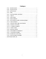
Page 30: ...BLY 10 FIG 7 MAIN HARNESS 12 FIG 8 ELECTRIC PARTS AND COMPONENTS 13 FIG 9 HYDRAULIC SYSTEM 16 FIG 10 CYLINDER ASSEMBLY 20 FIG 11 PUMP SYSTEM 21 FIG 12 DRIVING SYSTEM 22 FIG 13 INSTRUMENTS BOARD ASSEMB...

Page 31: ...3 Fig 1 Main components...

Page 32: ...ank cover 1 9000002023 Single mast 570X2000 9000002092 Single mast 570X1600 9000005952 Single mast 685X2000 9000005959 Single mast 685X1600 9000002108 Double mast 570X2900 9000005964 Double mast 685X2...

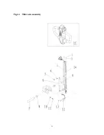
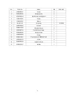
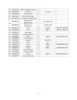
Page 33: ...9000002010 1 Single mast 570 9000005949 1 Single mast 685 9000002102 1 Double mast 570 1 9000005962 Welded fork 1 Double mast 685 2 2530402002 Bearing 4 3 0000026013 Circlip for shaft A type 4 4 25005...

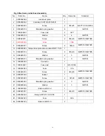
Page 34: ...3001 Sleeve 1 5 0000026010 Circlip 1 6 0000024015 Self locking nut 1 7 2000401007 Wheel frame 1 8 0000023111 Bolt 1 9 2000413002 Shaft sleeve 1 10 1000525001 Washer 2 11 0000027001 Bearing 2 12 202041...

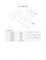
Page 35: ...7 Fig 4 Load wheel No Parts No Name Qty Remarks 1 2000416003 Load wheel 1 2 0000028055 Dowel pin heavy 2 3 1030507004 Axle 1 4 0000027001 Bearing 2 5 1000525001 Washer 2...

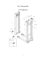
Page 36: ...8 Fig 5 Mast Assembly 5 1 Double Mast...

Page 37: ...00026013 Circlip for shaft A type 4 5 2500525001 Helical washer 2 Quality depends on situation 6 2500502003 Side cushion 4 7 0000023172 Screw 4 8 0000025001 Standard spring washer 4 9 0000023047 Screw...

Page 38: ...10 Fig 6 Electronic control board assembly...

Page 39: ...re protection module BD W 115 N 1 11 0000023516 Screw 2 12 0000025014 Flat washer 2 13 0000025015 Spring washer 2 14 1000404005 Connector 1 15 1000434021 One position vehicle fuse holder BD 1 16 10004...

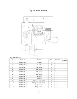
Page 40: ...ire 1 3 9000002411 1B wire 1 4 9000002412 2B wire 1 5 9000002413 3B wire 1 6 9000002414 4B wire 1 7 9000002415 PB wire 1 8 9000002416 B wire 1 9 9000002417 Driving wheel harness 1 10 9000002418 Charge...

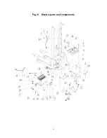
Page 41: ...13 Fig 8 Electric parts and components...

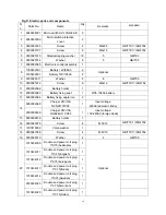
Page 42: ...t voltage 220AC 14 9000008638 Charger 24V 10A QQE240 11CH59 1 Input voltage 100 240AC 15 9000008678 Accumulator holder 1 Change 16 0000023076 Screw 6 17 1000418002 Valve washer 1 18 0000023056 Screw 4...

Page 43: ...023042 Screw 2 29 9000005937 Cable holder 1 30 1010434007 air fan ADDA DC12V 1 31 0000023041 Screw 2 32 1010404005 Connector 1 33 1000434021 One position vehicle fuse holder BD 1 34 1010434008 Plug fu...

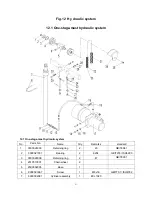
Page 44: ...ulic system No Parts No Name Qty Remarks 1 0000026003 Circlip for shaft 2 2 0000027001 Bearing 2 3 0000026009 Circlip for hole 2 4 2510510001 Chain wheel 2 5 2500502005 Cylinder joint 1 6 0000023067 S...

Page 45: ...KW2 0 volume 1 18 0000017002 O type ring plane seal joint J 1 19 9000002083 High pressure rubber tube 1 20 0000024087 I type nut 4 21 0000025079 Flat washer 2 22 0000028011 Cotter pin 2 23 2500502007...

Page 46: ...arts No Name Qty Remarks 1 0000026003 Circlip for shaft 2 2 0000027001 Bearing 2 3 0000026009 Circlip for hole 2 4 2510510001 Chain wheel 2 5 0000023067 Screw 1 9000002122 ECL1029 9000009971 ECL1032 6...

Page 47: ...00017002 Joint JTJ8 G3 8 M16x1 5 1 18 9000002082 High pressure rubber tube 1 19 0000024087 I type nut 2 20 0000025079 Flat washer 2 21 0000028011 Cotter pin 2 22 2500502007 End chainman 2 23 000002811...

Page 48: ...00322001 Dust ring 1 2 2000322002 Support ring for shaft 1 3 0000024074 I type nut Fin thread 1 4 0000025033 Spring washer 1 5 2010322001 Y type sealing ring 1 6 2000322003 Support ring for hole 1 7 0...

Page 49: ...2 2500217001 Oil suction pipe 1 3 2500237001 Gear pump 1 4 2500222001 O ring 1 5 2500237005 Refill cover 1 6 2500215002 Center valve block 1 7 2110234001 solenoid valve 1 8 2500235002 Overflow valve 1...

Page 50: ...0000023059 Screw 3 2 0000025019 Flat washer 3 3 9000002090 Driving wheel cover 1 4 0000023044 Screw 3 5 0000023089 Screw 1 6 9000002089 Handle seat 1 7 9000002087 Locating sleeve 1 8 0000023042 Screw...

Page 51: ...Roller bearing 1 12 9000002085 Connecting flange 1 13 0000023034 Screw 4 14 0000023006 Spring washer 10 15 0000025010 Spring washer 4 16 9000002088 Locating block 1 17 9000001023 Driving wheel 1 18 00...

Page 52: ...434001 DC power switch ZDK31 250 1 3 9000002070 Instruments cover 1 4 9000002071 Clipboard 1 0000024002 I type nut 4 5 0000023075 Screw 4 6 0000025011 Flat washer C level 4 7 0000023089 Screw 4 8 1010...

Page 53: ...25 Fig 14 Tiller arm assembly...

Page 54: ...3001 Screw 1 5 1030418001 Sleeve 1 6 9000007398 Air spring 1 F 800N 7 9000005945 Spindle 1 8 0000013002 Shoulder sleeve 2 9 0000028163 Cylindrical pin heavy 1 10 0000025004 Spring washer 1 11 00000230...

Page 55: ...27 Fig 15 Economic tiller head...

Page 56: ...000023138 Sunk screw 4 14 0000023040 Screw 2 15 9000002178 Handle upper cover 1 16 9000002311 Micro switch fixing large part 1 17 9000002161 Micro switch SS 5GL2 4 18 0090000261 Self tapping screw 14...

Page 57: ...er ring 2 2 0000027068 Bearing 1 3 0000036005 Flat key A 1 5X18 4 9000002136 Bearing shaft 1 19EL100005 5 9000002137 Reduction box body 1 19EL100001 6 1070309001 Pinion 1 7 0000026004 Retainer ring 1...

Page 58: ...90000182 Screw 10 24 9000002142 Seal ring 1 19EL100011 25 1070302007 Gear box cover 1 26 0000028144 Cylindrical pin 2 27 0000023063 Screw 11 28 0090000183 Oil seal 1 29 1070335002 Electronmagnetic bra...

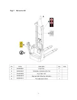
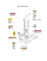
Page 59: ...U No Art No Description Qty Note A 9000005967 Sign hook 2 B 9000003923 Forbidden under above the fork 1 C 9000005968 Sign load curve 1 D 9000003570 Sign read and follow this instruction 1 E 9000003573...

Page 60: ...32 Fig 18 Sticker for US...

Page 61: ...on 1 G 9000003575 Sign warning stay clear stop truck 1 H 9000003576 Sign caution charger 1 I 9000003577 Sign danger battery 1 J 9000003578 Sign warning battery size 1 K 9000003579 Sign warning electri...

Page 62: ...1 ECL10 BPT 001 Version 02 2015 From truck identification number 30150200167 ECL 10M BPT 003 EN Spare parts list Electric Stacker ECL 10M...

Page 63: ...SSEMBLY 13 FIG 9 ELECTRONIC CONTROL BOARD ASSEMBLY 15 FIG 10 MAIN HARNESS 17 FIG 11 ELECTRIC PARTS AND COMPONENTS 18 FIG 12 HYDRAULIC SYSTEM 21 FIG 13 CYLINDER ASSEMBLY 25 FIG 14 PUMP SYSTEM 26 FIG 15...

Page 64: ...for EU No Art No Description Qty Note standard A 9000005967 Sign hook 2 B 9000003923 Forbidden under above the fork 1 C 9000005968 Sign load curve 1 D 9000003570 Sign read and follow this instruction...

Page 65: ...4 Fig 2 S ticker for US...

Page 66: ...this instruction 1 G 9000003575 Sign warning stay clear stop truck 1 H 9000003576 Sign caution charger 1 I 9000003577 Sign danger battery 1 J 9000003578 Sign warning battery size 1 K 9000003579 Sign...

Page 67: ...6 Fig 3 Appearance...

Page 68: ...mast 9000010166 Two stage mast 7 9000010168 Welded chassis 1 Two stage mast 9000007451 One stage mast 8 9000007476 Fork assembly 1 Two stage mast 9 9000007471 Welded right front leg 1 10 9000007466 W...

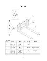
Page 69: ...080501001 Fork 2 950 1 2090501001 Fork 2 1150 2 9000007453 Fork holder 1 3 0000023088 Screw 3 M10x25 GB T70 1 ISO4762 4 2530402002 Roller 4 5 0000026013 Retaining ring 4 25 GB T894 1 6 2500525001 Wash...

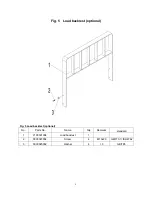
Page 70: ...Fig 5 Load backrest optional Fig 5 Load backrest optional No Parts No Name Qty Remarks standard 1 2100501004 Load backrest 1 2 0000023034 Screw 4 M10x20 GB T70 1 ISO4762 3 0000025002 Washer 4 10 GB T9...

Page 71: ...3 0000027013 Bearing 2 7206C DB GB T292 4 2000413001 Bushing 1 5 0000026010 Retaining ring 1 62 GB T893 1 6 0000024015 Nut 1 M14 GB T889 1 ISO7040 7 2000401007 Wheel frame 1 8 0000023111 Bolt 1 M14x1...

Page 72: ...T70 1 ISO4762 14 0000023006 Spring washer 4 10 GB T93 15 0000025002 Washer 4 10 GB T95 16 9000005936 Adjusting plate 4 1 2040400001 Steering wheel assembly 1 2 9000010408 steering wheel accessories 1...

Page 73: ...o Parts No Name Qty Remarks standard 1 2000416003 Load wheel 1 2 0000028055 Roll pin 2 5x40 GB T879 1 ISO8752 3 1030507004 Rotating axle 1 4 0000027001 Bearing 2 6204 GB T276 ISO3290 5 1000525001 Wash...

Page 74: ...13 Fig 8 Mast assembly 8 1 Two stage mast...

Page 75: ...B T894 1 5 2500525001 Washer 2 6 2500502003 Side cushion 4 7 0000023172 Screw 4 M8x30 GB T70 1 ISO4762 8 0000025001 Standard spring washer 4 8 GB T93 9 0000023047 Screw 2 M8x25 GB T70 1 ISO4762 10 253...

Page 76: ...15 Fig 9 Electronic control board assembly...

Page 77: ...985 Temperature protection module BD W 115 N 1 11 0000023516 Screw 2 M5x10 GB T818 ISO7045 12 0000025014 Washer 2 5 GB T95 13 0000025015 Standard spring washer 2 5 GB T93 14 1000404005 Connector 1 15...

Page 78: ...wire 1 2 9000002410 B wire 1 3 9000002411 1B wire 1 4 9000002412 2B wire 1 5 9000002413 3B wire 1 6 9000002414 4B wire 1 7 9000002415 PB wire 1 8 9000002416 B wire 1 9 9000002417 Driving wheel harness...

Page 79: ...18 Fig 11 Electric parts and components...

Page 80: ...06Ah battery 13 9000002064 Battery fixing angle iron 2 9000002068 Charger 24V 10A NCN24101P22 1 Input voltage 220AC domestic trade 14 9000008638 Charger 24V 10A QQE240 11CH59 1 Input voltage 100 240AC...

Page 81: ...2 M3X20 GB T70 1 ISO4762 28 0000023042 Screw 2 M6x10 GB T70 1 ISO4762 29 9000005937 Cable holder 1 30 1010434007 Fan ADDA DC12V 1 31 0000023041 Screw 2 M4x30 GB T818 ISO7045 32 1010404005 Connector h...

Page 82: ...No Parts No Name Qty Remarks standard 1 0000026003 Retaining ring 2 20 GB T894 1 2 0000027001 Bearing 2 6204 GB T276 ISO3290 3 0000026009 Retaining ring 2 47 GB T893 1 4 2510510001 Chain wheel 2 5 25...

Page 83: ...ure rubber tube 1 20 0000024087 Nut 4 M14 GB T6170 ISO4032 21 0000025079 Washer 2 14 GB T95 22 0000028011 Split pin 2 3x40 GB T91 ISO1234 23 2500502007 Chain tension bar 2 24 0000028110 Pin roll 2 6x4...

Page 84: ...Remarks standard 1 0000026003 Retaining ring 2 20 GB T894 1 2 0000027001 Bearing 2 6204 GB T276 ISO3290 3 0000026009 Retaining ring 2 47 GB T893 1 4 2510510001 Chain wheel 2 5 0000023067 Screw 1 M8x1...

Page 85: ...6170 ISO4032 20 0000025079 Washer 2 14 GB T95 21 0000028011 Split pin 2 3x40 GB T91 ISO1234 ISO1234 22 2500502007 Chain tension bar 2 23 0000028110 Pin roll 2 6x40 GB T880 24 0000028092 Split pin 2 1x...

Page 86: ...0322002 Support ring for shaft 1 40X10 2 3 0000024074 Nut 1 M20x1 5 GB T6171 ISO8673 4 0000025033 Standard spring washer 1 20 GB T93 5 2010322001 Y seal ring 1 45X35 6 6 2000322003 Support ring for ho...

Page 87: ...01 Oil tank 1 2 2500217001 Oil suction pipe 1 3 2500237001 Gear pump 1 4 2500222001 O ring 1 5 2500237005 Refill cover 1 6 2500215002 Center valve block 1 7 2110234001 solenoid valve 1 8 2500235002 Ov...

Page 88: ...27 Fig 15 Driving system...

Page 89: ...seat 1 7 9000002087 Locating bushing 1 8 0000023042 Screw 4 M6x10 GB T70 1 ISO4762 9 9000002086 Bearing seat 1 10 0000027048 Bearing 1 6209 GB T276 ISO3290 11 0090000038 Bearing 1 32011 GB T297 12 90...

Page 90: ...4001 DC power switch ZDK31 250 1 3 9000002070 Instruments board 1 4 9000002071 Clipboard 1 0000024002 Nut 4 M3 GB T6170 ISO4032 5 0000023075 Screw 4 M3x20 GB T70 1 ISO4762 6 0000025011 Washer 4 8 GB T...

Page 91: ...30 Fig 17 T iller arm assembly...

Page 92: ...X20 5 1030418001 Seal bushing 1 6 9000007398 Air spring 1 F 800N 7 9000005945 Rotating axle 1 20X78 8 0000013002 Shoulder harness 2 20X22X12 9 0000028163 Roll pin 1 4x35 GB T879 1 ISO8752 10 000002500...

Page 93: ...32 Fig 18 Economic tiller head...

Page 94: ...er downside cover 1 13 0000023138 Screw 4 M6X10 GB T70 3 ISO10642 14 0000023040 Screw 2 M6X16 GB T70 1 ISO4762 15 9000002178 Tiller upper cover 1 16 9000002311 Micro switch fixing large part 1 17 9000...

Page 95: ...ring 2 17 GB T894 1 2 0000027068 Bearing 1 6203 GB T276 ISO3290 3 0000036005 Flat key 1 A5X18 GB T1096 4 9000002136 Gear shaft 1 5 9000002137 Gear box 1 6 1070309001 Small gear 1 7 0000026004 Retaine...

Page 96: ...2 24 9000002142 Seal ring 1 19EL100011 25 1070302007 Gear box cover 1 26 0000028144 Roll pin 2 B6X20 GB T120 2 ISO8735 27 0000023063 Screw 11 M6X16 GB T70 1 ISO4762 28 0090000183 Oil seal 1 17X28X7 GB...

Page 97: ...0007398 Air spring 1 Fig 17 6 Tiller arm assembly 7 2000322002 Support ring for shaft 1 Fig 13 2 Cylinder assembly 8 0000022014 O seal ring 2 Fig 13 8 Cylinder assembly 9 0000022013 O seal ring 1 Fig...

Page 98: ...ents 18 9000002322 Relay 1 Fig 9 24 Electronic control board assembly 19 9000002190 Tiller micro switch assembly 1 1 Fig 18 30 Economic tiller head 20 9000002473 Tiller micro switch assembly 2 1 Fig 1...

Reviews: