background image


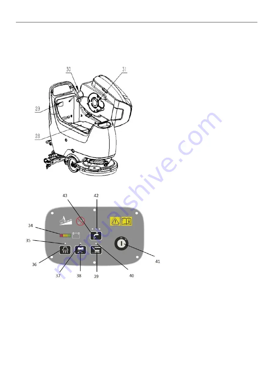
28. Battery  

29. Identification plate 

30. Tank rope 

31. Vacuum pressure plate 

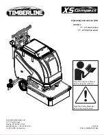
32. Balance adjusting knob 

33. Brush angle adjusting knob 

34. Battery indicator/ fault code display 

35. Vacuum motor button indicator 

36. Vacuum motor button  

37. Brush/pad driver indicator 

38. Brush/pad driver button  

39. Brush/pad driver removal button  

40. Brush/pad driver removal indicator 

41. Key switch 

42.


Solution flow indicator


43.


Solution flow button


Summary of Contents for NB530

Page 1: ...nd Floor Scrubber WARNING Do not operate the floor scrubber before reading and understanding the operator manual NOTE Please check product type and parameters of your scrubber in this manual as well a...

Page 2: ...L WIRING DIAGRAM 10 OPERATION INSTRUCTIONS 10 INSTALLING BATTERIES 10 INSTALLING AND REMOVING DISK BRUSHES PADS 11 ATTACHING SQUEEGEE ASSEMBLY 11 START AND STOP OF MACHINE 11 DRAINING TANKS 12 AFTER U...

Page 3: ...be completed by the technicians All instructions in this manual should be seriously followed otherwise our company shall not be liable for any losses arising therefrom HOW TO KEEP THE MANUAL This man...

Page 4: ...scrubber is not suitable for cleaning outdoors floors carpets or rough floors MACHINE IDENTIFICATION The model and serial number of this machine are marked on the identification label The information...

Page 5: ...potential hazard that may cause people injury and objects damage CAUTION It indicates a caution related to important or useful functions Pay attention to the paragraphs marked by this symbol NOTE It...

Page 6: ...t use the machine as a toy Be careful when there are children nearby The machine can only be used under the instructions manual and only the accessories approved by the company can be used Take precau...

Page 7: ...ons ensure that these are not due to lack of maintenance If necessary request assistance from the authorized personnel or from an authorized service center If the accessories really need to be replace...

Page 8: ...er 12 Recovery tank drain hose 13 Squeegee vacuum hose 14 Squeegee adjusting knob 15 Squeegee fixing knob 16 Squeegee blade 17 Squeegee lift lower foot pedal 18 Squeegee lifting lever 19 Charging sock...

Page 9: ...ngle adjusting knob 34 Battery indicator fault code display 35 Vacuum motor button indicator 36 Vacuum motor button 37 Brush pad driver indicator 38 Brush pad driver button 39 Brush pad driver removal...
Page 10: ...Float shut off screen holder 21 This fixes the floating shut off screen Solution tank fill port 22 This port makes filling water detergent low foam type easier to the solution tank Solution tank filt...

Page 11: ...ty L 50 Recovery tank capacity L 50 Front wheel diameter mm 200 Rear wheel diameter mm 100 Vacuum motor power W 400 Gradeability 2 Sound pressure level dB A 65 8 Battery maintenance free AGM 2 12V 24V...

Page 12: ...y connector and charger plug Handle the battery with great care This machine requires two 12V batteries please follow the solution water tank drawing for wiring INSTALLING BATTERIES M1 Brush Motor L2...

Page 13: ...ne forward to install the brush disk pad driver If necessary repeat this operation until the brush disk pad driver is installed 6 Depress the foot pedal 17 to lift the holder in order to remove the br...

Page 14: ...rns off depress the foot pedal 17 to raise the brush disk pad driver 15 Press the vacuum motor button 36 to turn off the vacuum motor After a delay of 5 seconds the vacuum motor is off for sucking up...

Page 15: ...en rinse the recovery tank with clean water Perform step 1 to step 4 7 Turn on the solution tank water tap 27 and drain the solution tank 6 Then rinse the tank with clean water AFTER USE After working...

Page 16: ...enance Table refer to the Service Manual that can be consulted at any service center REGULAR MAINTENANCE CHECKLIST Check Item Daily after use Weekly Semiannually Charge battery Clean squeegee Clean br...

Page 17: ...1 Clean the squeegee Fig 2 as shown in the previous paragraph 2 Check that the edge E Fig 2 of the front blade C and the edge F of the rear blade D they should be on the same horizontal level over the...

Page 18: ...ve the recovery tank lid 3 and rinse the lid 3 recovery tank 4 and the screen 20 with clean water Drain the sewage through the hose 12 4 If necessary loosen the buckle of the screen 20 clean the float...

Page 19: ...Turn off the key switch and cool the controller itself 2 Controller failed 3 Replace the controller 5 notches flash Open circuit of vacuum motor Open connection for vacuum motor Check the wiring of t...

Page 20: ...recovery tank lid is not correctly closed or the sealing is broken Close the lid correctly or replace the sealing Insufficient solution flow to the brush The solution clean water filter is dirty and...

Page 21: ...ttery X o o o X X Charger X o X o o o Chassis X o o o o o Electronic accessories X o X o X X Hose X o o X X o Motor X o o o X X Cable X o X X o o Basic parts o o o X o o Controller X o o o o o Treatme...

Reviews: