33
Monitoring of the battery continues when Pin 2 is turned off and the display is not lit. The hour meter
display is unaffected by Pin 2, although it cannot accumulate more time as long as the keyswitch pin is
not energized. The control inputs HRM (+) and HRM (–) are enabled by the keyswitch. Pin 2 is
connected to the vehicle’s keyswitch.
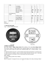
Pins 1 & 6
= Hour Meter Control. In normal operation, Pin 1 or 6 is connected and the other is left open.
Only one of these pins is connected when using normal hour meter function. It is possible to or the hour
meter between the two inputs so that it accumulates the total time either system is on. Hour meter
control logic is detailed in Table 2.
Pin 6
= Hour Meter +. HRM (+) (for use with a switched positive voltage). Pin 6 connects to a high
voltage as defined in Table 1. to activate the hour meter. Leaving Pin 6 open or connecting it to a low
voltage gives control of the hour meter to the Hour Meter (–) input. See Table 2.
Pin 1
= Hour Meter –. HRM (–) (for use with a switched ground). Pin 1 connects to a low voltage level as
defined in Table 1 to activate the hour meter. Leaving Pin 1 openor connecting it to high voltage gives
control of the hour meter to the Hour Meter (+) input.
Pin 3
= Relay. Pin 3 connects in series with the lift coil circuit (or the circuit to be switched at empty). For
holding relay (J), Pin 3 must be electrically closer to b than Pin 4
Pin 4
= Relay. Pin 4 also connects in series with the circuit to be switched at empty.
HOUR METER CONTROL LINES & IMPEDANCE SPECIFICATIONS
Low Voltage (max.)
Hight Voltage (min.)
Min. Impedance
HRM+
HRM-
5.0VDC
15.0VDC
80k
Ω
20 k
Ω
HOUR METER CONTROL LOGIC
Pin 1 (HRM-)
Pin 6 (HRM+)
Hour Meter Status
High
Low
Off
High
Open
Off
Open
Low
Off
Open
Open
Off
Low
High
On
Low
Low
On
Low
Open
On
High
High
On
Open
High
On
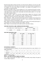
DISCHARGE ADJUSTMENTS
The followed table lists the voltages per cell under load that correspond to an empty indication on the
gauge (lockout point).
Setting
K
L
M
N
O
P
Q
R
S
T
U
Volt/Cell
at Empty
1.57
1.63
1.68
1.73*
1.78
1.82
1.84
1.86
1.89
1.91
1.93
NOTE: “*” – factory setting
RESET TYPE/LEVEL (AFTER OR DURING RECHARGE)
CTR = Charge Tracking Reset: If the gage is connected to the battery during recharge, the gage will
track the battery charge level.

