background image


13 

b. 

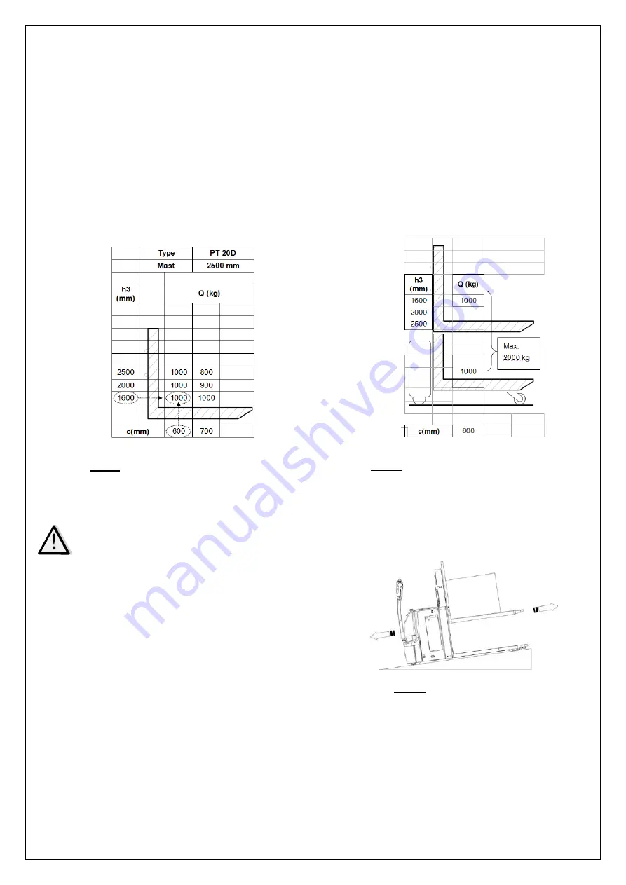
  Residual lift diagram 

The residual lift diagram indicates the maximum capacity Q [kg] for a given load centre c [mm] and the 

corresponding lift height H [mm] for the truck with horizontal load. 

The white markings on the mast indicate if the specific lifting limits reached. 

For instance with a load centre of gravity distance c of 600 mm and a maximum lift height H of 1600 mm, 

the max. Capacity Q is 1000 kg. 

Figure 8 shows when the truck is used as pallet truck and stacker at the same time, the 

load capacity of 

fork  and  pallet  is  both  1000kg,

 so the total 

load  capacity  is  2000kg.  When  the  fork  lift  height  is  within 

120mm, the maximum

 stack height is 1800mm.


c. 

Lifting 

 
DO NOT OVERLOAD! THE MAX. CAPACITY OF THIS TRUCK IS 2000KG 
 

Travel with the forks lowered fully underneath the pallet until 

lift  the load.  Press the  lifting button (19) until you reach  the 

desired lifting height. 


d. 

  Lowering 

Press the lowering button (19) carefully. 

Lower the load until the forks are near  the  chassis,  and  then 

drive the truck carefully out of the load area.   


Fig. 9: Load facing uphill 


Fig. 7: Residual lift diagram (stacking)    


Fig. 8: Residual lift diagram (double lifting)   

Summary of Contents for PT 20I

Page 1: ...Electric Pallet Truck WARNING Do not use the pallet truck before reading and understanding these operating instructions NOTE Please check the designation of your present type at the last page of this...

Page 2: ...1...

Page 3: ...oise level for this machine is 70 dB A according to EN 12053 ATTENTION Environmentally hazardous waste such as batteries oil and electronics will have a negative effect on the environment or health if...

Page 4: ...3...

Page 5: ...dual lift diagram 13 c Lifting 13 d Lowering 13 e Travelling 14 f Steering 14 g Braking 15 h Malfunctions 15 i Emergency 15 7 CHARGING AND REPLACEMENT OF BATTERY 15 a Replacement 16 b Battery indicato...

Page 6: ...must be placed approximately on the longitudinal centre plane of the truck Lifting or transporting people is forbidden If used on tail lifts or loading ramps please ensure that these are used correct...

Page 7: ...components 1 Safety belly button 2 Tiller 3 Main cover 4 Battery cover 5 Emergency button 6 Key switch 7 Indicator 8 Truck body 9 Battery 10 Switch 11 Mast 12 Support arms 13 Load roller 14 Mast 15 St...

Page 8: ...cl battery kg 855 990 1010 1060 2 2 Axle loading laden front rear kg 845 2010 880 2110 890 2120 925 2135 2 3 Axle loading unladen front rear kg 612 243 648 342 658 352 695 365 Tires chassis 3 1 Tires...

Page 9: ...1 3 6 2 Lift motor rating at S3 7 5 kW 2 2 6 3 Battery acc to DIN 43531 35 36 A B C 3VBS 6 4 Battery voltage nominal capacity K5 V Ah 24 210 6 5 Battery weight kg 185 6 6 Energy consumption acc to VD...

Page 10: ...V 5 Own mass self weight in kg without battery 6 Name and address of manufacturer 7 Battery weight minimum maximum 8 Nominal power in kW 9 Load center distance 10 Manufacturing data 11 Option 3 WARNIN...

Page 11: ...tinuous operation might cause damage of the power pack Stop operation if temperature of hydraulic oil is too high When operating the electric pallet truck the operator has to wear safety shoes The tru...

Page 12: ...and fasten the other side to the transporting truck c Decommissioning For storage remove the load lower the truck to the lowest position grease all in this handbook mentioned greasing points regular i...

Page 13: ...THE WARNINGS AND SAFETY INSTRUCTIONS CHAPTER 3 BE SURE THE GOODS ARE STABILITY PLACED ON THE PALLET AND MAKE DAILY CHECKS Make sure that the load is palletized and stable and that the daily inspectio...

Page 14: ...ker at the same time the load capacity of fork and pallet is both 1000kg so the total load capacity is 2000kg When the fork lift height is within 120mm the maximum stack height is 1800mm c Lifting DO...

Page 15: ...r starting the truck by turning on the key switch 6 move the tiller to the operating zone F fig 10 Turn the accelerator button to the desired direction forward Fw or backwards Bw fig 10 Control the tr...

Page 16: ...ns If there are any malfunctions or the truck is inoperative please stop using the truck and push the emergency button 5 If possible park the truck on a safe area and rotate the key 6 counterclockwise...

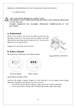
Page 17: ...Open the battery cover 20 disconnect the battery plug 22 and battery lock 21 then move the battery 23 out according to fig 11 Installation is in the reverse order of removal b Battery indicator Disch...

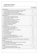
Page 18: ...ery plug with the plug on the truck and install the battery cover back 8 REGULAR MAINTENANCE Only qualified and trained personnel are allowed to do maintenance on this truck Before maintaining remove...

Page 19: ...lubricate the pivot points 14 Lubricate the grease nipples Electrical system 15 Inspect the electric wiring for damage 16 Check the electric connections and terminals 17 Test the emergency switch func...

Page 20: ...nts Lubricate the marked points according to the maintenance checklist The required grease specification is DIN 51825 standard grease c Check and refill hydraulic oil The required hydraulic fluid type...

Page 21: ...20 d Checking electrical fuses Remove the main cover The fuses are located in the position as fig 15 shows Table 4 Size of fuses Size FU1 10 A FU2 10 A FU01 350A Fig 15 Location fuses...

Page 22: ...ssive quantity of oil Reduce oil quantity Truck not starts operating Battery in charging Charge the battery completely and remove the main power plug form the electrical socket Battery is not connecte...

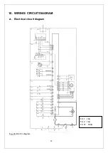
Page 23: ...22 10 WIRING CIRCUIT DIAGRAM a Electrical circuit diagram Fig 16 Electric diagram FU 1 10A FU 2 10A FU 01 350A...

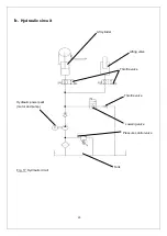
Page 24: ...23 b Hydraulic circuit Fig 17 Hydraulic circuit Lift cylinder Lifting valve Throttle valve Tank Loweing valve Throttle valve Pressure control valve Hydraulic power pack motor and pump...

Page 25: ...on in ASME B56 1 concerning the operator In this standard it is defined that the safe operation is the responsibility of the operator ASME B56 1 2003 Part II section 5 1 1 You and others can be seriou...

Page 26: ...l devices L Identification plate ID plate O Sign not under on forks P Sign danger being crushed Q Warning sticker R warning sticker The truck is equipped with an emergency button 5 which stops all lif...

Page 27: ...s instruction A Sign warning stay clear stop truck G Sign danger not riding J only for truck without foldable platform Sign danger battery I Sign oil filling point F Sign warning electrical devices K...

Page 28: ...27 Sign not under on forks O Sign Caution charger H Warning sticker R Warning sticker Q...

Page 29: ...ad front b10 in 20 1 3 7 Tread rear b11 in 15 0 Dimensions 4 2 Lowered mast height h1 in 33 7 46 4 54 3 48 5 4 4 Lift height h3 in 21 7 55 1 70 9 90 6 4 5 Extended Max height h4 in 61 3 99 5 115 3 136...

Page 30: ...nsumption acc to VDI cycle kWh h 1 0 Additional data 8 1 Type of drive control AC speed control 8 4 Sound level at driver s ear acc to EN 12053 dB A 69 1 in double deck operation mast lift 1 0t suppor...

Page 31: ...creazione della documentazione tecnica 2006 42 EG 2014 30 EU BG E N e podepsan t mto potvrzuje e podrobn popis uveden stroje odpov d Evropsk m sm rnic m 2006 42 EC sm rnice pro stroje a 2014 30 EU ele...

Page 32: ...anje tehni ne dokumentacije TR AB Uygunluk A klamas 1 Type Typ Tipo Modello Tyyppi Tipo Y T pus Tip Tips Tipas T p mza sahibi ah slar ayr nt lar belirtilen makine arac n n 2006 42 EC Makine Y nergesi...

Reviews: