background image

1

Speed Scrub

 – 

Wire Harness Group 

(page 2 of 4)

6

Summary of Contents for SpeedScrub Rider

Page 1: ... 331145 Rev 00 331145 SpeedScrub Rider Service Information and Hygenict Tanks Featuring ...

Page 2: ...The machine is operated with reasonable care D The machine is maintained regularly per the maintenance instructions provided D The machine is maintained with NOBLES supplied or approved parts Manual Number 331145 Revision 00 Published 12 04 Nobles and the FaST Foam Scrubbing Technology logo are United States registered trademarks of Tennant Company Copyright E 2004 NOBLES Printed in U S A ...

Page 3: ...ns 23 Operational Modes Interlocks 24 Diagnostic Fault Alarms 25 Alarm Codes 25 High Current Faults 25 Diagnostic Configuration Modes 26 Display Software Revision Mode 27 Self Test Mode 28 Input Display Mode 29 Manual Mode 30 Propel Brake Diagnostics 31 Battery Select Mode Voltage Levels 32 Battery Select Mode 32 Voltage Levels 32 Reverse Alarm Propel Speed Select Modes 33 Reverse Alarm Select Mod...

Page 4: ...ii ...

Page 5: ...working near Control Board Battery voltage is always present even with Key OFF Always unplug Positive Battery Cable when removing or replacing components Call Technical Services if Diagnostic Time Exceeds One Hour With Unknown Cause or Course of Action NOTE Troubleshooting charts may be shown with optional equipment The optional equipment may not be specified in these charts Some machines may not ...

Page 6: ... of Relay Diode Lamp Light Bulb Indicates Component is Energized Motor X Wiring Standoff Connection Point Horn or Alarm Terms Abbreviations BDI Battery Discharge Indicator Dynamic Braking A method of using the generating nature of an electric motor to slow the machine Hall Effect A voltage developed as a result of current flow in the presence of a magnetic field LED Light Emitting Diode PM Permane...

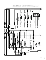
Page 7: ...1 2 3 4 5 1021038 Speed Scrub Ladder Schematic page 1 of 2 3 ...

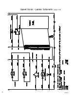
Page 8: ...1 2 3 4 5 1021038 Speed Scrub Ladder Schematic page 2 of 2 4 ...

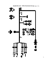
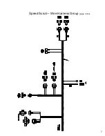
Page 9: ...1 Speed Scrub Wire Harness Group page 1 of 4 5 ...

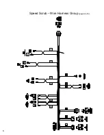
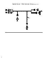
Page 10: ...1 Speed Scrub Wire Harness Group page 2 of 4 6 ...

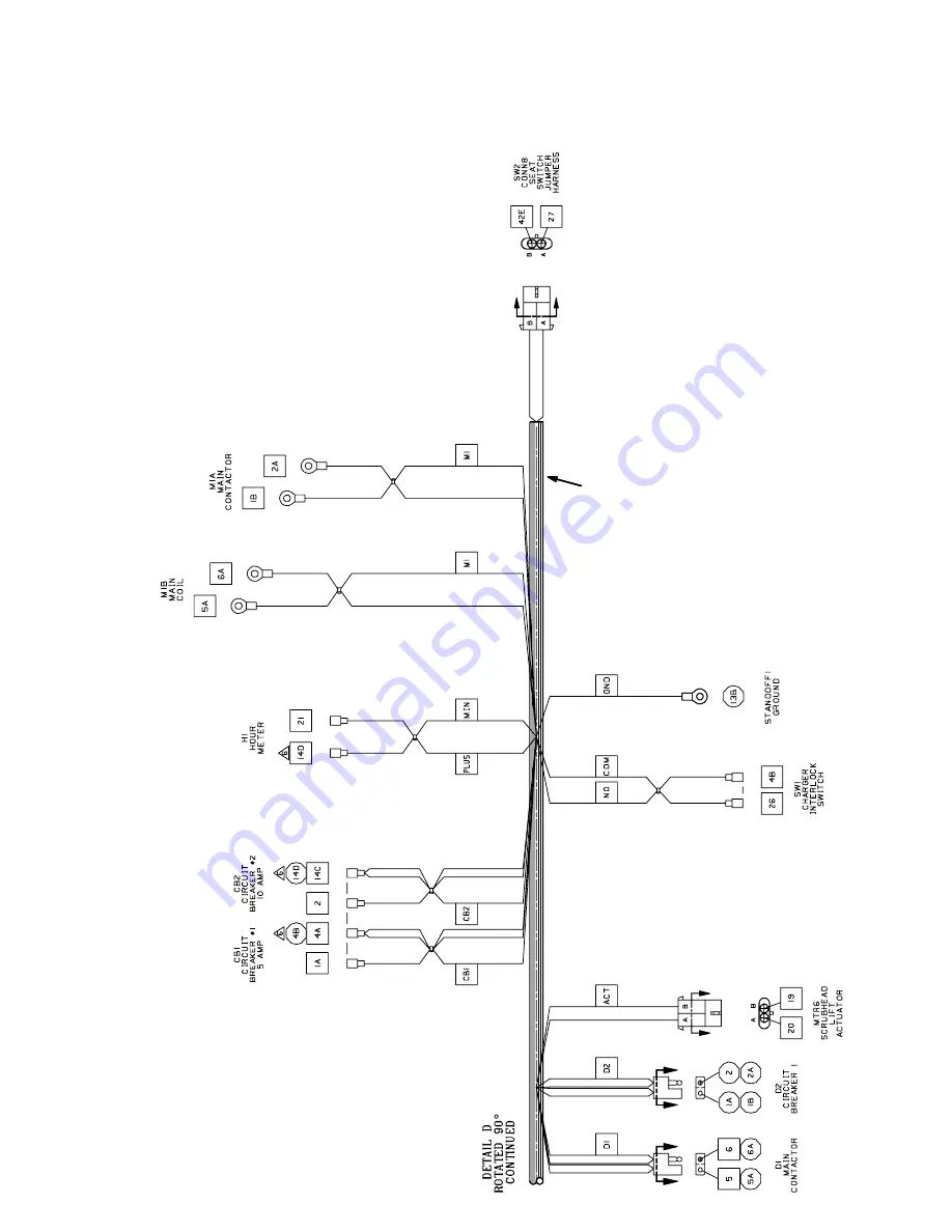
Page 11: ...1 Speed Scrub Wire Harness Group page 3 of 4 7 ...

Page 12: ...2 Speed Scrub Wire Harness Group page 4 of 4 8 ...

Page 13: ...ERGENCY STOP SWITCH X X 50 RED 2 2 14 MAIN CONTACTOR 6 5 5 5 6 3 26 3 26 4 4 4 4 4 PIN J6 17 PIN J6 5 PIN J6 24 PIN J6 6 PIN J6 13 14 1 RED 1 RED 13 BLK 50 RED 1 RED 13 BLK POST J11 POST J7 SW1 SW2 SEAT SWITCH PIN J6 35 PIN J6 7 42 42 27 LOGIC GROUND 32 ORG 27 GRN Wiring Color Codes Unless otherwise marked 0 1 2 3 4 5 6 7 8 9 Tan Pink Brown Orange Yellow Green Blue Purple Gray White Right Most Dig...

Page 14: ... EMERGENCY STOP SWITCH X X 50 RED 2 2 14 MAIN CONTACTOR 6 5 5 5 6 3 26 3 26 4 4 4 4 4 PIN J6 17 PIN J6 5 PIN J6 24 PIN J6 6 PIN J6 13 14 1 RED 1 RED 13 BLK 50 RED 1 RED 13 BLK POST J11 POST J7 SW1 SW2 SEAT SWITCH PIN J6 35 PIN J6 7 42 42 27 LOGIC GROUND 32 ORG 27 GRN Wiring Color Codes Unless otherwise marked 0 1 2 3 4 5 6 7 8 9 Tan Pink Brown Orange Yellow Green Blue Purple Gray White Right Most ...

Page 15: ...IN J6 5 PIN J6 24 PIN J6 6 PIN J6 13 14 1 RED 1 RED 13 BLK 50 RED 1 RED 13 BLK RIBBON CABLE CONNECTOR P6 POST J11 POST J7 CHARGER INTERLOCK 26 4 SW1 PIN J6 7 27 32 ORG 42 42 27 GRN SW2 SEAT SWITCH PIN J6 35 LOGIC GROUND v 6 VDC RIGHT SIDE DASH PANEL O I KEY SWITCH Indicates Component is Energized Wiring Color Codes Unless otherwise marked 0 1 2 3 4 5 6 7 8 9 Tan Pink Brown Orange Yellow Green Blue...

Page 16: ...TION TANK LOW SWITCH Recovery Tank Full Switch closes when recovery tank is full Solution Tank Low Switch opens when solution tank is low Tank Level Switches are ALWAYS in the OPEN position with low or empty tank Tank Level Switches are ALWAYS in the CLOSED position with full tank i Indicates Component is Energized Wiring Color Codes Unless otherwise marked 0 1 2 3 4 5 6 7 8 9 Tan Pink Brown Orang...

Page 17: ...r reverse or anytime Squeegee Vacuum Fan is ON Horn pulses when a fault is detected Directional Switch must be in FORWARD Position refer to Diagnostic Beep Code chart i CONDITIONS key ON operator on seat in motion OR Vacuum Fan running for Hour Meter 2 2 2 30 42 PIN J6 35 LOGIC GROUND 42 PIN J6 10 LS1 HORN H1 HOUR METER 14 23 14 14 14 21 RIGHT SIDE DASH PANEL HORN SWITCH M1B M1A 00000 NOTE Hour Me...

Page 18: ... REVERSE RIGHT SIDE DASH PANEL DIRECTIONAL SWITCH PIN J10 2 PIN J10 1 PIN J6 27 NEG POST J7 PIN J6 7 PIN J6 35 PIN J6 34 PIN J6 22 14 14 NOTE Brake Solenoid is energized to release parking brake 32 ORG 27 GRN MTR1B BRAKE SOLENOID Indicates Component is Energized Wiring Color Codes Unless otherwise marked 0 1 2 3 4 5 6 7 8 9 Tan Pink Brown Orange Yellow Green Blue Purple Gray White Right Most Digit...

Page 19: ... parking brake 32 ORG 27 GRN Speed Scrub Propel Reverse System CONDITIONS key ON operator on seat propel pedal depressed FORWARD REVERSE DIRECTIONAL SWITCH RIGHT SIDE DASH PANEL 6 VDC Indicates Component is Energized Wiring Color Codes Unless otherwise marked 0 1 2 3 4 5 6 7 8 9 Tan Pink Brown Orange Yellow Green Blue Purple Gray White Right Most Digit of Wire Number Color of Wire Battery Negative...

Page 20: ... M1B M1A PIN J10 2 PIN J10 1 NEG POST J7 PIN J6 7 PIN J6 35 PIN J6 33 14 14 32 ORG 27 GRN Indicates Component is Energized Wiring Color Codes Unless otherwise marked 0 1 2 3 4 5 6 7 8 9 Tan Pink Brown Orange Yellow Green Blue Purple Gray White Right Most Digit of Wire Number Color of Wire Battery Negative or Logic Ground Battery Positive or Positive Output MTR1B BRAKE SOLENOID NOTE Brake Solenoid ...

Page 21: ...OL BOARD STANDOFF 2 6 VDC 6 VDC 6 VDC 6 VDC v v 1 RED STANDOFF 4 NEG 50 RED F1 100 A S1 D1 CB1 5 A CB2 15 A KEYSWITCH EMERGENCY STOP SWITCH X 50 RED 14 MAIN CONTACTOR 6 5 5 5 6 3 26 3 4 4 4 4 PIN J6 17 PIN J6 5 PIN J6 24 PIN J6 6 PIN J6 13 14 1 RED 50 RED 13 BLK RIBBON CABLE CONNECTOR P6 POST J11 POST J7 CHARGER INTERLOCK 26 4 SW1 X 2 2 2 M1B M1A PIN J6 7 27 32 ORG 42 42 27 GRN SW2 SEAT SWITCH PIN...

Page 22: ...s Voltage at actuator connector will be approx 24 VDC for 4 seconds then approx 11 to 12 VDC for 2 to 4 seconds Pressing the One Step Scrub Button will lower the squeegee and scrub head Only one actuator will be energized at any given time squeegee is lowered first then the scrub head Squeegee actuator uses internal limit switches to stop travel in upward and downward travel Scrub head actuator tr...

Page 23: ...OARD STANDOFF 2 6 VDC 6 VDC 6 VDC 6 VDC v v 1 RED STANDOFF 4 NEG 50 RED F1 100 A S1 D1 CB1 5 A CB2 15 A KEYSWITCH EMERGENCY STOP SWITCH X 50 RED 14 MAIN CONTACTOR 6 5 5 5 6 3 26 3 4 4 4 4 PIN J6 17 PIN J6 5 PIN J6 24 PIN J6 6 PIN J6 13 14 1 RED 50 RED 13 BLK RIBBON CABLE CONNECTOR P6 POST J11 POST J7 CHARGER INTERLOCK 26 4 SW1 X 2 2 2 M1B M1A PIN J6 7 27 32 ORG 42 42 27 GRN SW2 SEAT SWITCH PIN J6 ...

Page 24: ... 6 VDC 6 VDC v v 1 RED STANDOFF 4 NEG 50 RED F1 100 A S1 D1 CB1 5 A CB2 15 A KEYSWITCH EMERGENCY STOP SWITCH X 50 RED 14 MAIN CONTACTOR 6 5 5 5 6 3 26 3 4 4 4 4 PIN J6 17 PIN J6 5 PIN J6 24 PIN J6 6 PIN J6 13 14 1 RED 50 RED 13 BLK RIBBON CABLE CONNECTOR P6 POST J11 POST J7 CHARGER INTERLOCK 26 4 SW1 X 2 2 2 M1B M1A PIN J6 7 27 32 ORG 42 42 27 GRN SW2 SEAT SWITCH PIN J6 35 LOGIC GROUND TOUCH PANEL...

Page 25: ...IC GROUND TOUCH PANEL RIBBON CABLE LEFT SIDE DASH PANEL One Step Scrub Button Pressing the One Step Scrub Button will activate FaST Pump Motor OR Solution Solenoid Valve as Scrub Brush Motors engage Pressing the FaST button will toggle from FaST scrubbing to Conventional scrubbing FaST system will operate ONLY if FaST LED is ON Solution Volume Control Buttons will NOT operate Solution Volume Contr...

Page 26: ...C GROUND TOUCH PANEL RIBBON CABLE LEFT SIDE DASH PANEL One Step Scrub Button 16 14 PIN J6 4 Indicates Component is Energized Wiring Color Codes Unless otherwise marked 0 1 2 3 4 5 6 7 8 9 Tan Pink Brown Orange Yellow Green Blue Purple Gray White Right Most Digit of Wire Number Color of Wire Battery Negative or Logic Ground Battery Positive or Positive Output 14 SOLUTION SOLENOID VALVE 16 Solution ...

Page 27: ...Speed Scrub LED Locations Descriptions 23 ...

Page 28: ...ge Red LED on Battery Gauge blinking Disable Scrub function Operator can get an additional minute of operation by re engaging scrub system with One Step button Fault LED ON and any one or more of the following Lower Brush Pressure 1 LED ON Right Motor Upper Brush Pressure 3 LED ON Left Motor Upper Solution Flow 3 LED ON Vacuum Fan Prevent damage to Scrub Brush Motors or Vacuum Fan Motor Scrub func...

Page 29: ...uts off Propel Interlock Parking Brake Unplugged FORWARD Controller sensed open circuit on parking brake Horn sounds 7 beep cycle repeats Also FAULT and Lower Solution Flow LED s blink Prevents movement of machine with ineffective parking brake Scrub function shuts off Propel Interlock E STOP Switch Activated FORWARD Controller sensed open circuit on Emergency Stop Switch circuit Horn sounds 8 bee...

Page 30: ... hold FaST and Increase Brush Pressure Buttons turn key switch ON release after battery LED s are OFF FaST LED ON if in Forward OR Vacuum Fan Squeegee LED ON if in Reverse Solution Flow LED s display position of Propel Pedal Brush Pressure LED s display position of Brake Pedal Battery LED s display Propel Motor current level Provides information regarding brake pedal signal propel pedal signal and...

Page 31: ...Brush Pressure LED blinks TENS of YEAR Lower Solution Flow LED blinks SINGLE YEAR Brush Pressure LED s of Blinks Solution Flow LED s of Blinks Revision Date Day 3 Upper 2 3 Upper 6 26th Month 2 Middle 1 2 Middle 1 November Year 1 Lower 0 LED OFF 1 Lower 4 2004 TOUCH PANEL LEFT SIDE DASH PANEL Brush Pressure Increase Button Solution Flow Increase Button DAY MONTH YEAR LED 3 LED 2 LED 1 LED 3 LED 2 ...

Page 32: ...o table below If any LED other than One Step is lit solid a SHORT FAULT was found refer to table below Self Test Results LED Flashing OPEN Solid SHORT System at Fault One Step LED No Faults Found FaST LED Fast Pump Vacuum Fan Squeegee LED Vacuum Fan 3 Upper Brush Pressure LED Right Brush 2 Middle Brush Pressure LED Left Brush 1 Lower Brush Pressure LED Head Actuator 3 Upper Solution Flow LED Water...

Page 33: ...VATED switch is CLOSED Horn will repeat 8 beep cycle when Emergency Stop Switch is activated One Step Button One Step LED Scrub system IS ACTIVATED Scrub system IS NOT ACTIVATED Vacuum Fan Squeegee Button Vacuum Fan Squeegee LED Vacuum Fan Squeegee ARE ACTIVATED Vacuum Fan Squeegee ARE NOT ACTIVATED Battery Voltage 1 Red Battery LED Battery needs charging LED is BLINKING Battery has sufficient cha...

Page 34: ...e Solution Flow Rate Decrease Solution Flow Press Release Solution Flow LED s In this mode the Solution Flow automatic ON OFF interlock is disabled When the Solution Empty switch is un grounded for a short time the Solution Empty LED will light If the Recovery Full LED or the Solution Empty LED is ON and the Scrub System or Vacuum Fan Squeegee system is activated the Recovery Full LED and Solution...

Page 35: ...edal No LED s indicate the pedal is released 3 LED s indicate that the pedal is fully depressed Propel Motor Current Depress Accelerator Pedal Battery LED s Battery gauge LED s display the current level being drawn by the Propel Motor Each LED represents 7 Amps of current ex 3 LED s 21 Amps Propelling System Data Direction Wire Color Polarity 25 Green 24 Yellow 25 Green 24 Yellow Releasing the Pro...

Page 36: ... x x x x x x x x x x x G G Y R Voltage Levels Battery Level Worldwide Voltage Wet European Voltage Wet TNV Voltage Wet Worldwide Voltage Gel BDI Indicator LED s Full Battery Voltage 24 5 24 5 24 5 24 5 Level 4 23 8 23 9 23 9 24 0 Level 3 23 1 23 2 23 3 23 5 Level 2 22 4 22 6 22 7 23 0 Level 1 21 7 21 9 22 1 22 6 Full discharge 21 0 21 3 21 6 22 2 Voltage measured at circuit board Assume 0 5 Volts ...

Page 37: ...up Alarm is sounding Normal mode has been selected Cycle key switch OFF then ON again Verify correct mode has been chosen Propel Speed Select Mode Propel Speed Select Mode allows selection of maximum forward speed during scrubbing TO ENTER Press and hold FaST Button Turn key switch ON Release Buttons after selecting desired Brush Pressure LED Refer to table below for speed selection BRUSH PRESSURE...

Page 38: ... will DISABLE Output Activating Vacuum Fan OR Propelling machine will enable the Hour Meter Horn will sound when Directional Switch is selected for Reverse except in Hospital Mode Parking Brake activated after timer has expired Outputs Inputs and the Outputs they Control Directional Switch Reverse Directional Switch Forward Throttle Input Pedal pressed Brake Input Pedal pressed Horn Button Pressed...

Page 39: ... 24 9 11 8 164 12 16 40 47 17 23 10 190 20 26 50 60 31 41 1 4 250 4 5 5 6 7 10 7 10 10 13 6 8 17 19 5 16 312 7 9 9 12 15 20 15 20 20 26 13 15 32 38 3 8 375 13 17 16 21 27 35 36 47 22 26 65 75 7 16 438 20 26 26 34 43 56 53 76 33 39 106 124 1 2 500 27 35 39 51 65 85 89 116 48 56 162 188 5 8 625 80 104 130 170 171 265 228 383 3 4 750 129 168 215 280 313 407 592 688 1 1 000 258 335 500 650 757 984 128...

Page 40: ...00 55 000 60 000 SAE Grade 2 Carriage Bolts Low or Medium Carbon Steel 1 4 Thru 3 4 Over 3 4 Thru 1 1 2 55 000 33 000 57 000 74 000 36 000 60 000 Stainless Steel 18 8 Austenitic Stainless Steel 50 000 90 000 SAE Grade 5 Medium Carbon Steel Quenched Tempered 1 4 Thru 1 Over 1 to 1 1 2 85 000 74 000 92 000 81 000 120 000 105 000 Socket Screws High Carbon Alloy Steel Quenched Tempered 136 000 160 000...

Page 41: ...7 5 9 8 Nm M8 8 1 10 5 Nm 18 5 24 Nm 26 2 34 Nm 31 40 Nm M10 16 21 Nm 37 48 Nm 52 67 Nm 63 81 Nm M12 28 36 Nm 64 83 Nm 90 117 Nm 108 140 Nm M14 45 58 Nm 102 132 Nm 142 185 Nm 169 220 Nm M16 68 88 Nm 154 200 Nm 219 285 Nm 262 340 Nm M20 132 171 Nm 300 390 Nm 424 550 Nm 508 660 Nm N E W T O N C E N T I M E T E R S N E W T O N M E T E R S M22 177 230 Nm 409 530 Nm 574 745 Nm 686 890 Nm M24 227 295 Nm...

Page 42: ...el Austenitic Stainless Steel 8 8 Hex Head Grade 5 Medium Carbon Steel Quenched Tempered 10 9 Hex Head Flat Head Grade 8 12 9 Socket Head Class 190 27 550 PSI 240 34 800 PSI 330 47 850 PSI 400 58 000 PSI 340 49 300 PSI 420 60 900 PSI 450 65 300 PSI 700 101 000 PSI M16 M16 640 92 800 PSI 800 116 000 PSI 660 95 700 PSI 830 120 350 PSI Medium Carbon Steel Quenched Tempered 940 136 300 PSI 1040 150 80...

Page 43: ... 8 7 8 1 4 28 4 6 5 6 5 16 18 8 14 13 14 5 16 24 9 14 13 14 3 8 16 12 18 15 18 3 8 24 12 18 16 18 1 2 13 26 40 37 40 1 2 20 27 42 41 42 5 8 11 58 89 73 89 5 8 18 60 92 82 92 Torque Standard Nylon Insert Lock Nuts Nut Hex Light THIN Cad or Zinc Plated Torque in Foot Pounds 39 ...

Page 44: ...ndle nut to 12 ft lbs while turning the wheel assembly forward by hand to fully seat the bearings 2 Back off the nut to the just loose position 3 Hand tighten the spindle nut Loosen the spindle nut until either hole in the spindle lines up with a slot in the nut Not more than 1 2 flat 4 Install the cotter pin Bend the ends of the cotter pin against the nut cut off extra length to ensure ends will ...

Page 45: ...ximum torque is Tighten the slotted nut to a lower torque and then tighten the nut to align the cotter pin hole with the slot on the nut Do not exceed the recommended torque Do not back off the nut to align the holes Motor Tapered Shaft Nut Info Torque Specification Recommendations A H Series 1 00 dia 75 16 UNF 150 ft lb dry 1 107 Hex 125 ft lb lubricated Plus torque to align for pin 2000 Series 1...

Page 46: ...commended Seating Torque 250 10 24 312 45 In Lbs 1 4 20 9 Ft Lbs 375 5 16 18 19 Ft lbs 500 3 8 16 32 Ft Lbs 625 1 2 13 82 Ft Lbs 750 5 8 11 164 Ft Lbs Nominal Diameter Thread Size Recommended Seating Torque 6 8 7 Nm M6x1 0 12 Nm 10 M8x1 25 29 Nm 12 M10x1 5 57 Nm 16 M12x1 75 100 Nm M5x0 8 Metric 42 ...

Page 47: ...r large end of bushing do not hammer bushing directly 6 Repeat steps 4 and 5 until torque wrench reading after hammering is the same as before hammering 7 Fill all unoccupied holes with grease To Remove 1 Remove all setscrews 2 Insert setscrews in holes indicated by D on the diagram Loosen bushing by alternately tightening setscrews 3 To reinstall complete all seven 7 steps installation steps Reco...

Page 48: ...nner that even stress is set up throughout at the same time allowing the parts to be drawn together so that their mating surfaces will contact 5 1 3 4 2 6 1 2 5 3 6 4 1 2 3 4 5 6 Torque in Steps 1 Run each fastener in proper sequence up to the recommended torque 2 Repeat the process of running up each fastener in proper sequence up to the recommended torque 3 If necessary repeat step two until all...

Reviews: