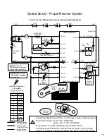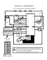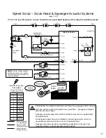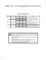
28
29
42
42
RECOVERY TANK
FULL SWITCH
LOGIC GROUND
42
SW3
SW4
D3
1 RED
13 BLK
14
13 BLK
2
POS
CONTROL BOARD
STANDOFF 2
+
-
6 VDC
+
-
6 VDC
+
-
6 VDC
v
M1B
v
1 RED
1 RED
CHARGER
PLUG
STANDOFF 4
13 BLK
NEG
TOUCH
PANEL
50 RED
F1
100 A
S1
M1A
D1
CB1
5 A
CB2
15 A
KEYSWITCH
+
RIBBON CABLE
-
EMERGENCY
STOP SWITCH
X
X
50 RED
2
2
14
MAIN
CONTACTOR
6
5
5
5
6
3
26
3
4
4
4
4
PIN J6-17
PIN J6-5
PIN J6-24
PIN J6-6
PIN J6-13
14
1 RED
1 RED
13 BLK
50 RED
1 RED
13 BLK
RIBBON CABLE CONNECTOR P6
POST J11
POST J7
CHARGER INTERLOCK
26
4
SW1
v
+
-
6 VDC
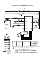
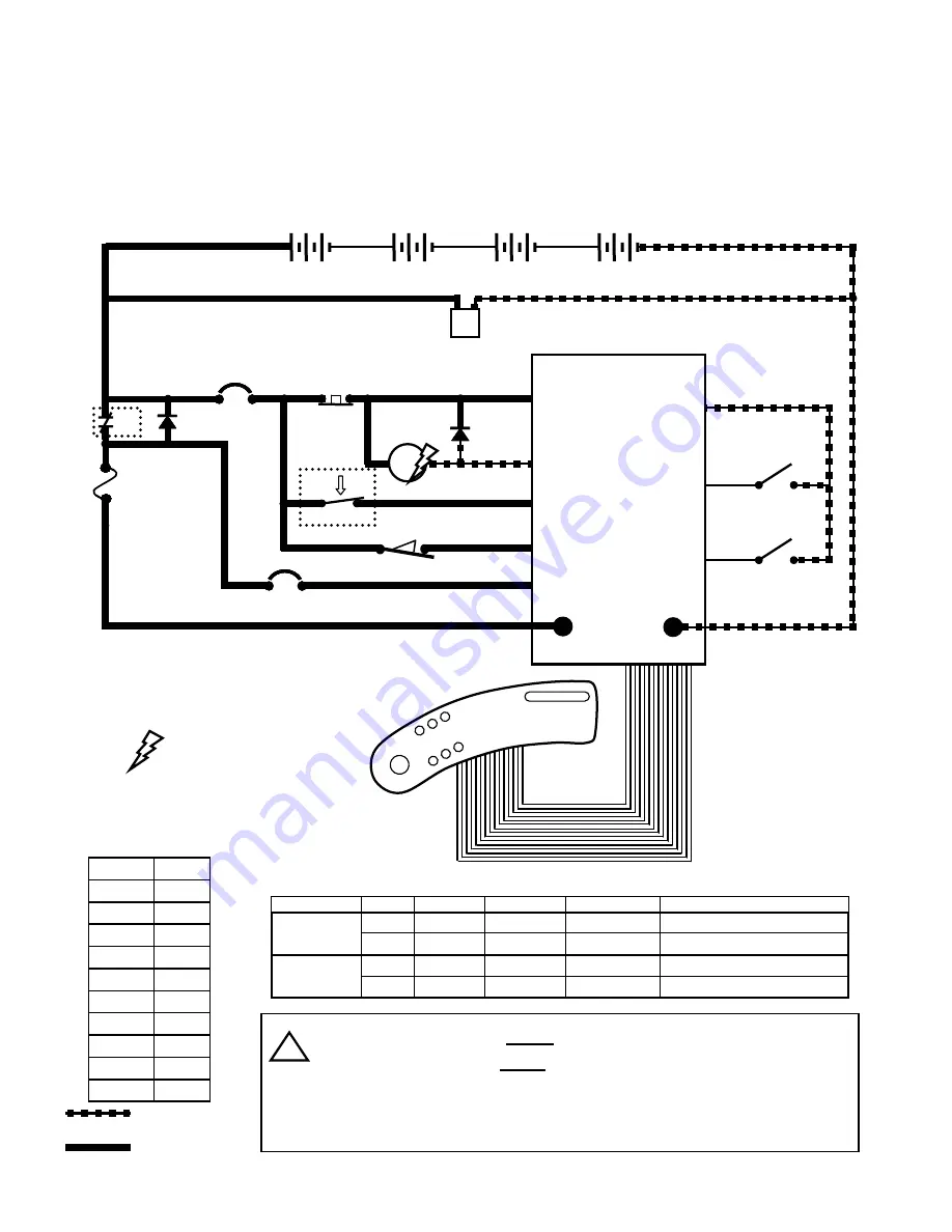
Speed Scrub – Tank Level Switches
CONDITIONS:
key ON
PIN J6-20
PIN J6-35
PIN J6-8
SOLUTION TANK
LOW SWITCH
Recovery Tank Full Switch
closes
when recovery tank is full
Solution Tank Low Switch
opens
when solution tank is low
Tank Level Switches are ALWAYS in the OPEN position with low or
empty tank
Tank Level Switches are ALWAYS in the CLOSED position with full tank
i
Indicates Component
is Energized
Wiring Color Codes
(Unless otherwise marked)
0
1
2
3
4
5
6
7
8
9
Tan
Pink
Brown
Orange
Yellow
Green
Blue
Purple
Gray
White
Right Most Digit
of Wire Number
Color of Wire
= Battery Negative
or Logic Ground
= Battery Positive
or Positive Output
switch
tank full
tank empty switch OPEN switch CLOSED
indicator
x
x
Solution Tank Empty LED OFF
x
x
Solution Tank Empty LED ON
x
x
Recovery Tank Full LED ON
x
x
Recovery Tank Full LED OFF
Solution Tank
Recovery Tank
Tank Level Switches Logic Chart
12
Summary of Contents for SpeedScrub Rider
Page 1: ... 331145 Rev 00 331145 SpeedScrub Rider Service Information and Hygenict Tanks Featuring ...
Page 4: ...ii ...
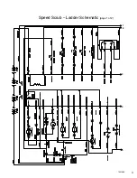
Page 7: ...1 2 3 4 5 1021038 Speed Scrub Ladder Schematic page 1 of 2 3 ...
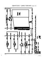
Page 8: ...1 2 3 4 5 1021038 Speed Scrub Ladder Schematic page 2 of 2 4 ...
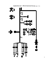
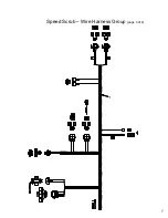
Page 9: ...1 Speed Scrub Wire Harness Group page 1 of 4 5 ...
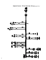
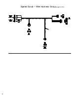
Page 10: ...1 Speed Scrub Wire Harness Group page 2 of 4 6 ...
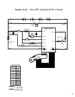
Page 11: ...1 Speed Scrub Wire Harness Group page 3 of 4 7 ...
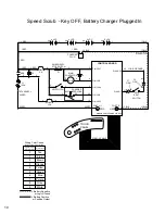
Page 12: ...2 Speed Scrub Wire Harness Group page 4 of 4 8 ...

