13 BLK
13 BLK
27
42
42
SW2
SEAT
SWITCH
LOGIC GROUND
14
PROPEL PEDAL
POSITION SENSOR
31
PROPEL
SIGNAL
POWER
GND
42
14
X
35
PROPEL
DIRECTION
SWITCH
42
42
REVERSE
FORWARD
HALL
EFFECT
SENSOR
PROPEL MOTOR
FORWARD
24
25
24 WHT
25 BLK
25
14
MTR1A
15
15
14
14
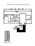
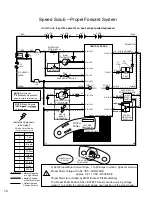
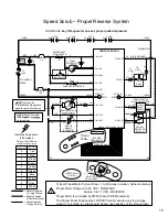
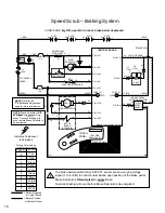
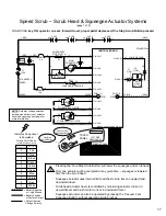
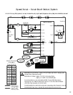
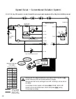
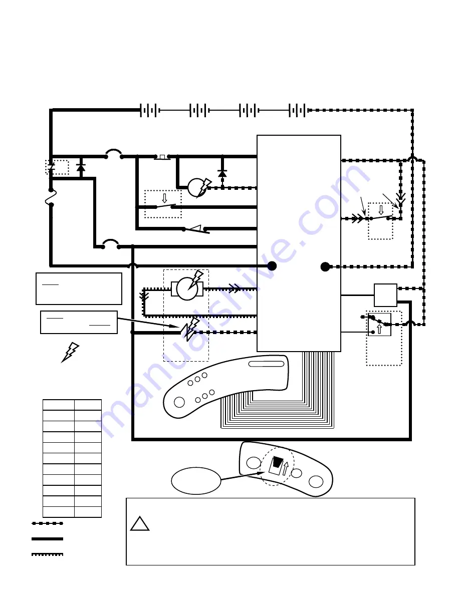
Speed Scrub – Propel Forward System
CONDITIONS:
key ON, operator on seat, propel pedal depressed
D3
1 RED
13 BLK
POS
CONTROL BOARD
STANDOFF 2
+
-
6 VDC
+
-
6 VDC
+
-
6 VDC
+
-
6 VDC
v
v
1 RED
STANDOFF 4
TOUCH
PANEL
50 RED
F1
100 A
S1
D1
CB1
5 A
CB2
15 A
KEYSWITCH
RIBBON CABLE
EMERGENCY
STOP SWITCH
X
50 RED
14
MAIN
CONTACTOR
6
5
5
5
6
3
26
3
4
4
4
4
PIN J6-17
PIN J6-5
PIN J6-24
PIN J6-6
PIN J6-13
14
1 RED
50 RED
RIBBON CABLE CONNECTOR P6
POST J11
CHARGER INTERLOCK
26
4
SW1
X
+
LEFT SIDE
DASH PANEL
2
2
2
M1B
M1A
i
FORWA
RD
REVE
RSE
RIGHT SIDE
DASH PANEL
DIRECTIONAL
SWITCH
PIN J10-2
PIN J10-1
PIN J6-27
NEG
-
POST J7
PIN J6-7
PIN J6-35
PIN J6-34
PIN J6-22
14
14
NOTE
: Brake Solenoid
is
energized
to
release
parking brake.
32
ORG
27
GRN
MTR1B
BRAKE
SOLENOID
Indicates Component
is Energized
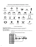
Wiring Color Codes
(Unless otherwise marked)
0
1
2
3
4
5
6
7
8
9
Tan
Pink
Brown
Orange
Yellow
Green
Blue
Purple
Gray
White
Right Most Digit
of Wire Number
Color of Wire
= Battery Negative
or Logic Ground
= Battery Positive
or Positive Output
= Output that can
Change Polarity
Typical Propel Motor Current Draw: 1 to 20 Amps in motion, higher at start-up
Propel Motor Voltage: 0 to 24 VDC - FORWARD
Approx. 0 to 17 VDC - REVERSE
Propel Motor is controlled by PWM (Pulse Width Modulation)
The Propel Pedal Position HALL EFFECT Sensor sends a varying voltage
signal (1 to 4 Volts) to control board, based upon position of the propel pedal
NOTE
: Refer to the
“Propel/Brake Diagnostics”
page for more information
SW6
U2
14
Summary of Contents for SpeedScrub Rider
Page 1: ... 331145 Rev 00 331145 SpeedScrub Rider Service Information and Hygenict Tanks Featuring ...
Page 4: ...ii ...
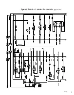
Page 7: ...1 2 3 4 5 1021038 Speed Scrub Ladder Schematic page 1 of 2 3 ...
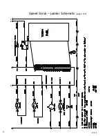
Page 8: ...1 2 3 4 5 1021038 Speed Scrub Ladder Schematic page 2 of 2 4 ...
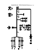
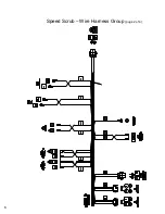
Page 9: ...1 Speed Scrub Wire Harness Group page 1 of 4 5 ...
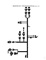
Page 10: ...1 Speed Scrub Wire Harness Group page 2 of 4 6 ...
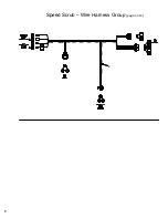
Page 11: ...1 Speed Scrub Wire Harness Group page 3 of 4 7 ...
Page 12: ...2 Speed Scrub Wire Harness Group page 4 of 4 8 ...


