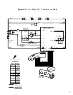

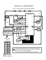

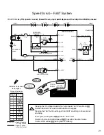

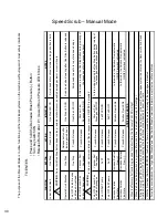
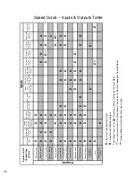
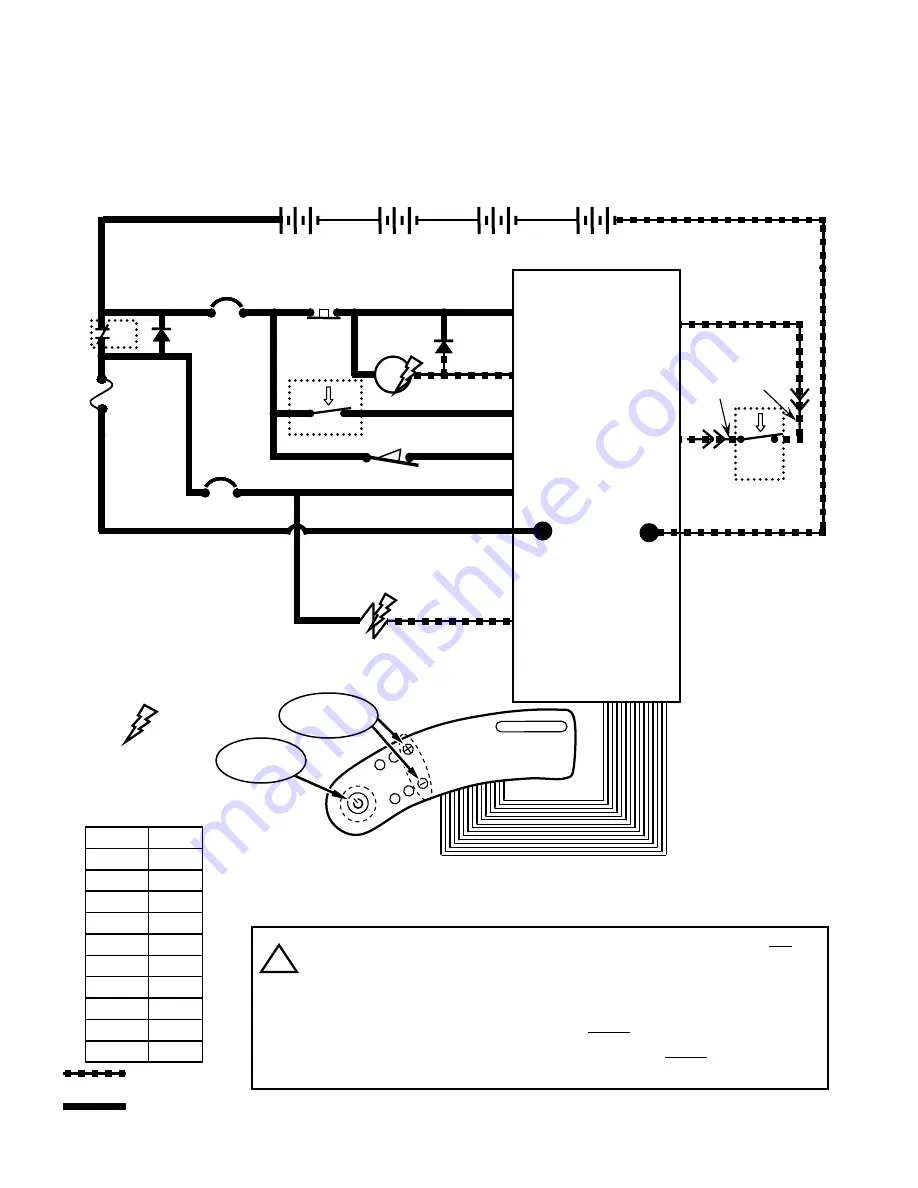
Speed Scrub – Conventional Solution System
CONDITIONS:
key ON, operator on seat, forward travel, propel pedal depressed, One Step Scrub Button pressed
D3
1 RED
13 BLK
13 BLK
POS
CONTROL BOARD
STANDOFF 2
+
-
6 VDC
+
-
6 VDC
+
-
6 VDC
+
-
6 VDC
v
v
1 RED
STANDOFF 4
NEG
50 RED
F1
100 A
S1
D1
CB1
5 A
CB2
15 A
KEYSWITCH
-
EMERGENCY
STOP SWITCH
X
50 RED
14
MAIN
CONTACTOR
6
5
5
5
6
3
26
3
4
4
4
4
PIN J6-17
PIN J6-5
PIN J6-24
PIN J6-6
PIN J6-13
14
1 RED
50 RED
13 BLK
RIBBON CABLE CONNECTOR P6
POST J11
POST J7
CHARGER INTERLOCK
26
4
SW1
X
+
2
2
2
M1B
M1A
PIN J6-7
27
32
ORG
42
42
27
GRN
SW2
SEAT
SWITCH
PIN J6-35
LOGIC GROUND
TOUCH
PANEL
RIBBON CABLE
LEFT SIDE
DASH PANEL
One Step
Scrub Button
16
14
PIN J6-4
Indicates Component
is Energized
Wiring Color Codes
(Unless otherwise marked)
0
1
2
3
4
5
6
7
8
9
Tan
Pink
Brown
Orange
Yellow
Green
Blue
Purple
Gray
White
Right Most Digit
of Wire Number
Color of Wire
= Battery Negative
or Logic Ground
= Battery Positive
or Positive Output
14
SOLUTION SOLENOID VALVE
16
Solution Volume
Control Buttons
Pressing the “One Step Scrub Button” will activate FaST Pump Motor
OR
Solution Solenoid Valve as Scrub Brush Motors engage
Pressing the FaST button will toggle from FaST scrubbing to Conventional
scrubbing
Conventional Solution system will operate
ONLY
if FaST LED is OFF
Solution Volume Control Buttons & LED’s will operate
ONLY
during
Conventional scrubbing
i
SOL2
22
Summary of Contents for SpeedScrub Rider
Page 1: ... 331145 Rev 00 331145 SpeedScrub Rider Service Information and Hygenict Tanks Featuring ...
Page 4: ...ii ...
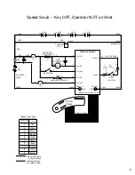
Page 7: ...1 2 3 4 5 1021038 Speed Scrub Ladder Schematic page 1 of 2 3 ...
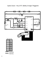
Page 8: ...1 2 3 4 5 1021038 Speed Scrub Ladder Schematic page 2 of 2 4 ...
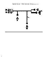
Page 9: ...1 Speed Scrub Wire Harness Group page 1 of 4 5 ...
Page 10: ...1 Speed Scrub Wire Harness Group page 2 of 4 6 ...
Page 11: ...1 Speed Scrub Wire Harness Group page 3 of 4 7 ...
Page 12: ...2 Speed Scrub Wire Harness Group page 4 of 4 8 ...