


Table of Contents
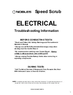
Electrical Troubleshooting Information ...................................................................................... 1
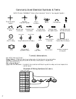
Commonly Used Electrical Symbols & Terms........................................................................ 2
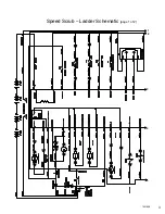
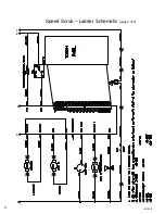
Ladder
Schematic .................................................................................................................. 3
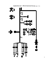
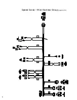
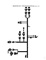
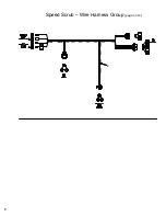
Wire
Harness Group............................................................................................................... 5
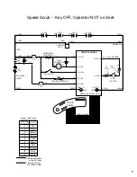
Key OFF, Operator NOT on Seat........................................................................................... 9
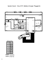
Key OFF, Battery Charger Plugged In ................................................................................. 10
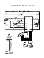
Key ON, Operator on Seat ................................................................................................... 11
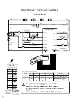
Tank
Level Sensors.............................................................................................................. 12
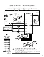
Horn & Hour Meter Systems ................................................................................................ 13
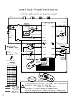
Propel
Forward System........................................................................................................ 14
Propel
Reverse System........................................................................................................ 15
Braking
System .................................................................................................................... 16
Scrub Head & Squeegee Actuator Systems ........................................................................ 17
Scrub Brush Motors System................................................................................................. 19
Vacuum
Fan System ............................................................................................................ 20
FaST
System........................................................................................................................ 21
Conventional Solution System................................................................................................. 22
LED Locations & Descriptions.............................................................................................. 23
Operational
Modes & Interlocks ........................................................................................... 24
Diagnostic & Fault Alarms .................................................................................................... 25
Alarm
Codes ..................................................................................................................... 25
High
Current Faults ........................................................................................................... 25
Diagnostic & Configuration Modes ....................................................................................... 26
Display
Software
Revision Mode ......................................................................................... 27
Self Test Mode ..................................................................................................................... 28
Input
Display Mode............................................................................................................... 29
Manual
Mode........................................................................................................................ 30
Propel / Brake Diagnostics ................................................................................................... 31
Battery Select Mode & Voltage Levels................................................................................. 32
Battery
Select Mode.......................................................................................................... 32
Voltage Levels................................................................................................................... 32
Reverse Alarm & Propel Speed Select Modes .................................................................... 33
Reverse
Alarm
Select Mode ............................................................................................. 33
Propel
Speed
Select Mode ............................................................................................... 33
Inputs & Outputs Table......................................................................................................... 34
Torque Standard...................................................................................................................... 35
Inch
Fasteners...................................................................................................................... 35
METRIC
Fasteners............................................................................................................... 37
Nylon
Insert Lock Nuts ......................................................................................................... 39
Nut-Hex
Light THIN .............................................................................................................. 39
Wheel
Bolt and Nuts............................................................................................................. 40
Wheel
Bearing
Adjustment................................................................................................... 40
Tightening
Nuts
on Tapered Shafts ..................................................................................... 41
Shoulder
Bolts ...................................................................................................................... 42
Taper
Lockr Bushings .......................................................................................................... 43
Sequence
Tightening ........................................................................................................... 44
i
Summary of Contents for SpeedScrub Rider
Page 1: ... 331145 Rev 00 331145 SpeedScrub Rider Service Information and Hygenict Tanks Featuring ...
Page 4: ...ii ...
Page 7: ...1 2 3 4 5 1021038 Speed Scrub Ladder Schematic page 1 of 2 3 ...
Page 8: ...1 2 3 4 5 1021038 Speed Scrub Ladder Schematic page 2 of 2 4 ...
Page 9: ...1 Speed Scrub Wire Harness Group page 1 of 4 5 ...
Page 10: ...1 Speed Scrub Wire Harness Group page 2 of 4 6 ...
Page 11: ...1 Speed Scrub Wire Harness Group page 3 of 4 7 ...
Page 12: ...2 Speed Scrub Wire Harness Group page 4 of 4 8 ...


