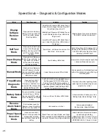
Speed Scrub – Diagnostic & Configuration Modes
Mode
Entry Sequence
Indicator
Function
Upper Brush Pressure LED blinks Tens of
days of month, Upper Solution Flow LED
blinks Single day of month
Middle Brush Pressure LED blinks Tens of
month, Middle Solution Flow LED blinks
Single month
Lower Brush Pressure LED blinks Tens of
year, Lower Solution Flow LED blinks out
Single year
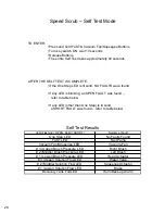
Self Test
Mode
Press and hold FaST and
Vacuum Fan/Squeegee
Buttons, turn key switch ON,
wait 10 seconds, release
buttons
Start of test - Left Scrub Brush turns ON
End of test - Horn sounds
Solid lit One Step LED indicates OK, A
Flashing LED indicates an OPEN Fault,
A Solid lit LED (other than One Step)
indicates a SHORT Fault
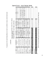
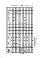
Input Display
Mode
Press and hold Decrease
Solution Flow (-) Button, turn
key switch ON, release
button after forth battery
LED starts to blink
Fourth battery LED blinks
Shows state of control board inputs from
various switches and sensors
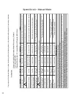
Manual Mode
Press and hold Decrease
Brush Pressure (-) Button,
turn key switch ON, release
after Lowest Brush Pressure
LED starts to blink.
Lowest down pressure LED will blink
Allows operation of individual functions
without the safety interlocks affecting or
controlling them
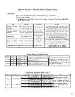
Propel/Brake
Diagnostic
Mode
Press and hold FaST
and Increase Brush
Pressure (+) Buttons, turn
key switch ON, release after
battery LED's are OFF
FaST LED ON if in Forward
OR
Vacuum
Fan/Squeegee LED ON if in Reverse -
Solution Flow LED's display position of
Propel Pedal, Brush Pressure LED's display
position of Brake Pedal, Battery LED's
display Propel Motor current level
Provides information regarding brake
pedal signal, propel pedal signal, and
propel motor current
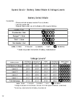
Battery Select
Mode
Press and hold the Increase
Solution Flow (+) Button,
turn key switch ON, release
after one Battery LED starts
to blink
Any one of lower 4 battery LED’s blinks
Allows selection of battery type. See
“Battery Select Mode Settings” table.
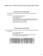
Reverse
Alarm Select
Mode
Put directional switch in
Reverse, press & hold Horn
Button, turn key switch ON
Horn sounds or is silent
Allows enable/disable of
Backup alarm (Hospital Mode)
Propel Speed
Selection
Mode
Press and hold FaST
Button, turn key switch ON,
release after selecting
desired Brush Pressure LED
setting
Brush Pressure Lower, Middle, and Upper
LED’s represents LOW, MEDIUM and HIGH
maximum Forward Propel Speed selection
Allows selection of maximum forward
speed during scrubbing
LOWER (#1) LED = 2.0 mph / 3.2 kph
MIDDLE (#2) LED = 2.7 mph / 4.3 kph
UPPER (#3) LED = 3.5 mph / 5.5 kph
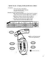
Display
Software
Revision
Mode
Press and hold One Step
Button, turn key switch ON,
wait 10 seconds, release
One Step Button
Blinking Brush Pressure and Solution
Flow LED’s indicate revision date
26
Summary of Contents for SpeedScrub Rider
Page 1: ... 331145 Rev 00 331145 SpeedScrub Rider Service Information and Hygenict Tanks Featuring ...
Page 4: ...ii ...
Page 7: ...1 2 3 4 5 1021038 Speed Scrub Ladder Schematic page 1 of 2 3 ...
Page 8: ...1 2 3 4 5 1021038 Speed Scrub Ladder Schematic page 2 of 2 4 ...
Page 9: ...1 Speed Scrub Wire Harness Group page 1 of 4 5 ...
Page 10: ...1 Speed Scrub Wire Harness Group page 2 of 4 6 ...
Page 11: ...1 Speed Scrub Wire Harness Group page 3 of 4 7 ...
Page 12: ...2 Speed Scrub Wire Harness Group page 4 of 4 8 ...

