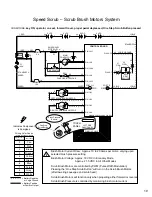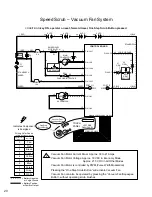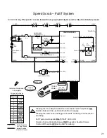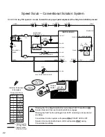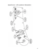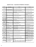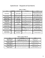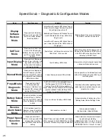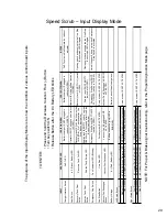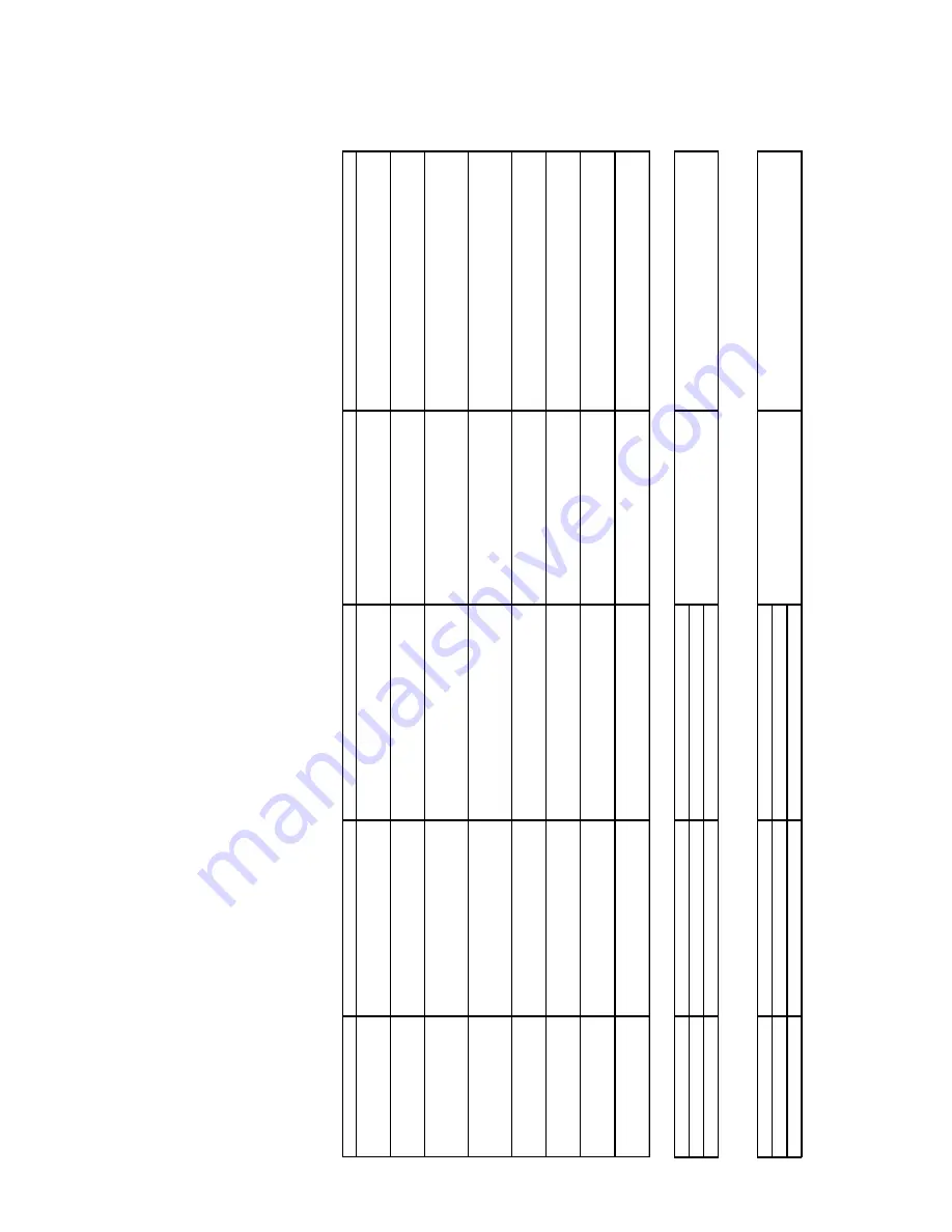
Speed Scrub – Input Display Mode
INPUT
A
SSO
CIA
T
ED LED
LED
IS O
N
WH
E
N
:
L
E
D
IS O
FF W
H
EN
:
NOTES
C
h
ar
ge
r Inte
rl
oc
k
Sw
it
c
h
F
a
ST
LE
D
Bat
ter
y
c
h
a
rger IS
NO
T
pl
ugged
in
(s
w
itc
h
is CLO
S
E
D
)
B
a
ttery
c
harger
IS pl
ugge
d i
n
(s
w
itc
h
is O
P
E
N
)
FaST
sy
stem
w
ill
s
ti
ll operate, b
u
t w
ithou
t
indi
c
a
tor
Seat S
w
it
c
h
#
5 (
G
re
e
n
) B
a
ttery
LED
O
perator IS
N
O
T
s
itti
ng on seat (s
w
itc
h
is
O
P
EN
)
Oper
a
tor
IS
s
itti
ng on
Seat (s
w
itch is
CLOSE
D
)
R
e
c
o
v
e
ry
T
a
n
k
Fl
oat
Sw
it
c
h
Rec
o
v
e
ry
T
ank
F
u
ll LE
D
Rec
o
v
e
ry
tank
IS FULL (s
w
itc
h
m
u
s
t b
e
CLO
S
ED f
o
r 5
to 7 s
e
c
onds af
te
r O
n
e
Ste
p
But
ton i
s
ac
ti
v
a
ted
)
Rec
o
v
e
ry
t
ank
IS NO
T
F
U
LL (s
w
itch
is O
P
E
N
)
O
peni
ng sw
it
c
h
an
d pus
h
ing
the the
O
ne S
tep
B
u
tton turns
L
E
D of
f a
gain
Sol
u
ti
on T
ank
Fl
oat
Sw
it
c
h
Sol
u
ti
on T
ank
E
m
pty
LE
D
S
o
lu
tio
n
tank
IS
EMP
T
Y
(s
w
itc
h m
u
s
t be
OPE
N
f
o
r 5 to 7
s
e
c
ond
s
af
ter
One S
tep
Button
is ac
ti
v
a
ted
)
S
o
lut
ion
tank
IS NOT
EMP
T
Y
(s
w
itc
h i
s
CLO
S
ED)
Clo
s
in
g s
w
it
c
h
and pushi
ng the th
e O
ne
Step
Button
tur
n
s
LE
D
of
f agai
n
Em
ergency
S
top S
w
it
c
h
F
a
u
lt In
dicator LED (Bl
in
k
ing)
E
m
er
g
enc
y
St
op Sw
it
c
h
IS
ACT
IV
A
T
E
D
(s
w
itc
h i
s
O
P
EN)
Em
er
gen
c
y
Stop
Sw
itch IS NOT
A
C
TI
V
A
TE
D
(
s
w
it
c
h
i
s
C
L
O
S
E
D
)
Hor
n
w
ill
repeat 8
beep cy
cle w
hen E
m
ergenc
y
Stop
Sw
it
c
h
is ac
ti
v
a
ted
O
ne S
tep B
u
tton
O
ne S
tep L
E
D
S
c
ru
b
s
y
s
tem
I
S
A
C
T
IVA
T
E
D
S
c
rub s
y
s
tem
IS NOT
ACT
IV
A
T
E
D
Vac
u
um
Fan/Sq
ueegee
Button
Va
c
uum
Fan/S
queeg
ee LE
D
Vac
u
um
Fan &
Sque
egee A
R
E
A
C
TI
V
A
TE
D
V
a
c
u
u
m
F
a
n & S
queeg
ee ARE
NO
T
A
C
TI
V
A
TE
D
Battery
Vol
tag
e
#
1 (
R
ed) Ba
tter
y
LE
D
B
a
ttery
n
eeds
char
gi
ng
(L
E
D
is
BL
INKING
)
Ba
tter
y
ha
s
s
u
ff
ic
ient char
g
e
le
vel
Lef
t Sc
rub
B
rus
h
Low
Pres
s
u
re
#
1
(Lo
w
e
r)
B
rush Pres
s
u
re
LE
D
L
O
W
sc
ru
b
br
ush c
u
rr
en
t s
ensed
Me
diu
m
Pres
s
u
re
# 2
(Mi
ddl
e
)
Br
u
s
h P
res
sur
e
LED
M
EDIUM
s
c
ru
b
brus
h c
u
rr
e
nt s
ensed
Hi
g
h Pres
s
u
re
#
3
(U
pp
er
) Brus
h P
ress
u
re LED
H
IGH s
c
rub brus
h cur
rent s
e
ns
ed
R
ight Sc
rub
B
rush
Low
Pres
s
u
re
# 1
(Low
er
) So
lut
ion
F
low
L
E
D
L
O
W
sc
ru
b
br
ush c
u
rr
en
t s
ensed
Me
diu
m
Pres
s
u
re
# 2
(Mi
ddl
e
) S
o
lu
ti
on F
low
LED
M
EDIUM
s
c
ru
b
brus
h c
u
rr
e
nt s
ensed
Hi
g
h Pres
s
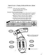
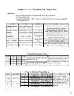
TO ENTER:
• Press and hold the Decreas
e Soluti
on Flow (-) Button
• Turn key switch ON
•
R
elease Button after the
# 4 Battery LED bli
n
ks
The purpose of the Input Displ
ay
Mode is to show the conditi
on
of vari
ous control board i
n
puts
NOTE: For Propel & Brake si
gnal
trou
bl
esh
o
o
tin
g
, refe
r to the Pro
p
el Di
ag
nostics Mod
e
p
a
g
e
u
re
# 3
(U
pp
er
) S
o
lu
ti
on Flow
LE
D
H
IGH s
c
rub brus
h cur
rent s
e
ns
ed
S
c
ru
b
s
y
s
te
m
I
S
N
O
T A
C
TI
V
A
TE
D
S
c
ru
b
s
y
s
te
m
I
S
N
O
T A
C
TI
V
A
TE
D
29
Summary of Contents for SpeedScrub Rider
Page 1: ... 331145 Rev 00 331145 SpeedScrub Rider Service Information and Hygenict Tanks Featuring ...
Page 4: ...ii ...
Page 7: ...1 2 3 4 5 1021038 Speed Scrub Ladder Schematic page 1 of 2 3 ...
Page 8: ...1 2 3 4 5 1021038 Speed Scrub Ladder Schematic page 2 of 2 4 ...
Page 9: ...1 Speed Scrub Wire Harness Group page 1 of 4 5 ...
Page 10: ...1 Speed Scrub Wire Harness Group page 2 of 4 6 ...
Page 11: ...1 Speed Scrub Wire Harness Group page 3 of 4 7 ...
Page 12: ...2 Speed Scrub Wire Harness Group page 4 of 4 8 ...

