

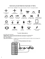

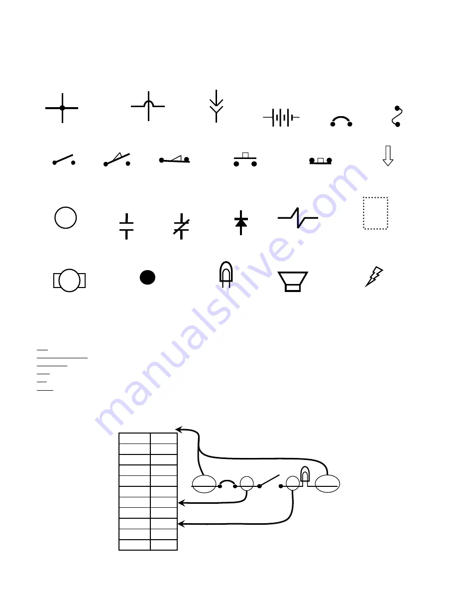
Commonly Used Electrical Symbols & Terms
NOTE: The term “NORMALLY” refers to the components’ “at rest” or “de-energized” position
+
-
Battery
Fuse
Normally Closed
Push-Button Switch
Normally Open
Switch
Wires Connected
Together
Normally Open
Push-Button Switch
Plug-in
Connection
Wires Not
Connected Together
Circuit Breaker
Indicates Movement
from Normal Position
Normally Open
Limit Switch
Normally Closed
Limit Switch
Indicates Component in
Position Other than Normal
Relay Contacts (Part 2 of Relay)
Normally Open
Normally Closed
Solenoid (Valve
or Actuator)
M1
Relay Coil
(Part 1 of Relay)
Diode
Lamp
(Light Bulb)
Indicates Component
is Energized
Motor
X
Wiring Standoff
(Connection Point)
Horn or Alarm
Terms & Abbreviations
BDI – Battery Discharge Indicator
Dynamic Braking – A method of using the generating nature of an electric motor to slow the machine
Hall Effect – A voltage developed as a result of current flow in the presence of a magnetic field
LED – Light Emitting Diode
PM – Permanent Magnet
PWM (Pulse Width Modulation) – A method of using controlled on/off times to regulate the voltage and current supplied to an
electrical device
Wiring Color Codes
(Unless otherwise marked)
0
1
2
3
4
5
6
7
8
9
Tan
Pink
Brown
Orange
Yellow
Green
Blue
Purple
Gray
White
Right Most Digit
of Wire Number
Color of Wire
Example of Wiring Numbers & Colors:
1 RED
25
7
13 BLK
2
Summary of Contents for SpeedScrub Rider
Page 1: ... 331145 Rev 00 331145 SpeedScrub Rider Service Information and Hygenict Tanks Featuring ...
Page 4: ...ii ...
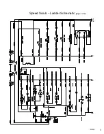
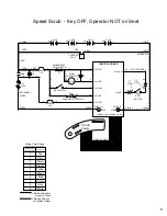
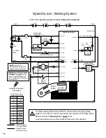
Page 7: ...1 2 3 4 5 1021038 Speed Scrub Ladder Schematic page 1 of 2 3 ...
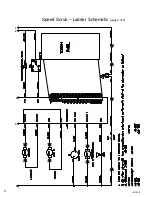
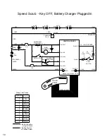
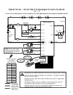
Page 8: ...1 2 3 4 5 1021038 Speed Scrub Ladder Schematic page 2 of 2 4 ...
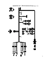
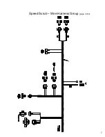
Page 9: ...1 Speed Scrub Wire Harness Group page 1 of 4 5 ...
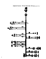
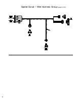
Page 10: ...1 Speed Scrub Wire Harness Group page 2 of 4 6 ...
Page 11: ...1 Speed Scrub Wire Harness Group page 3 of 4 7 ...
Page 12: ...2 Speed Scrub Wire Harness Group page 4 of 4 8 ...


