background image

 19


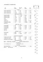
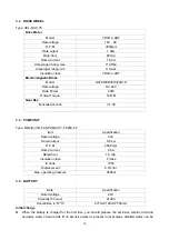
3.3  DRIVE WHEEL  

 
Type: 3EL-DC-0.75 

Drive Motor 

Model YDQ1.3-4BT 

Rate voltage 

16V  AC 

R.P.M 3200rpm 

Rate output 

1.3kw 

Rate hour 

60min. 

Rated current 

76.2A 

Amperager rating- max 

110.7HZ 

Amperager rating- min 

H class 

Insulation class 

YDQ1.3-4BT 

Electromagnetic Brake 

Model G072-REB0510(20)P-R 

Rate voltage 

DC 24V 

Rate Power 

30W 

Output Torque 

16N·M 

Gear Box 

transmission ratio 

i=1:30 


3.4 PUMP 

UNIT 


Type: MR2-B-V1B-F4.5-PCMAV1Y-TK05C-F2 

Item Specification 

Rated voltage 

24V 

Rated output 

0.8 kw 

R.P.M 2500 

rpm 

Rated current 

60 A 

Rated hour 

1.8 min. 

Insulation class 

F class 

IP Code


IP54 

Displacement 0.7cc/rec 

Max. operating pressure 

250bar 


3.5  BATTERY 


Rate  

Specification 

Rated voltage 

24V 

Capacity (5 hours) 

210Ah 

Overall size (L*W*H) 

677mm*196mm*555mm 

Initial charge 

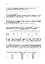
  When the battery is charged for the first time, you should prepare the exclusive sulfuric acid and 

excluslve water of lead acids (lf no excusive water is present in local areas, distilled water can be 

Summary of Contents for LPT22

Page 1: ...NOBLELIFT EQUIPMENT Service Maintenance Manual LPT22 Power Pallet Truck V LPT22 01 00 Date 2011 02 26 ...

Page 2: ... ELECTRICAL PLUG 43 4 HYDRAULIC SYSTEM 44 4 1 HYDRAULIC FLOW DIAGRAM 44 4 2 INSTALLATION OF HYDRAULIC SYSTEM 44 4 3 REPLACING THE POWER UNIT 45 4 4 REPLACING THE CYLINDER 46 4 5 CLEANING OIL TANK AND FILTER 47 4 6 TROUBLE DIAGNOSTICS 48 5 DRIVE WHEEL 50 5 1 REPLACING THE DRIVE SYSTEM AND WHEEL 51 5 2 REPLACING THE CARBON BRUSH KIT 52 5 3 REPLACING THE BRAKE 52 5 4 THE BRAKE CLEARANCE ADJUSTMENT 52...

Page 3: ...ping must be collected and disposed of in an environment friendly way and in accordance with the directives of respective countries Such work must be carried out in areas intended for this purpose Recyclable material should be taken care of by specialized authorities Environmentally hazardous waste such as oil filters batteries and electronics will have a negative effect on the environment or heal...

Page 4: ...NE MANUFACTURER HAS NO DIRECT CONTROL OVER THE FIELD INSPECTION AND MAINTENANCE SAFETY IN THIS AREA RESPONSIBILITY OF THE OWNER OR OPERATOR FAILURE TO COMPLY WITH SAFETY PRECAUTIONS LlSTED IN THIS SECTION MAY RESULT IN MACHINE DAMAGE PERSONNEL INJURY OR DEATH AND IS A SAFETY VIOLATION When carrying out any operation or maintenance have trained and experienced personnel carry out the work When carr...

Page 5: ...tery plug DO NOT WEAR LONG HAIR UNRESTRAINED OR LOOSE FITTING CLOTHING AND NECKTIES WHICH ARE APT TO BECOME CAUGHT ON OR ENTANGLED IN EQUIPMENT During maintenance do not allow any unauthorized person to stand near the machine Flames should never be used instead of lamps Never use a buring flame to check leaks or the level of oil or electrolyte Immediately remove any oil or grease on the floor of t...

Page 6: ...es or skin immediately flush it with large quantities of water When working on the battery wear goggles or safety glasses If splashed into the eyes flush with water and get medical attention immediately Battery terminals touched by metal objects can cause short circuit and burn you Keep tools away from the terminals When disassembling and assembling the battery make sure that the battery terminals...

Page 7: ...ny dirt or dust into the system Use only approved nonflammable cleaning solvents When changing the oil or fitter check the drained oil and filter for any signs of excessive metal particles or other foreign materials Always use NOBLELIFT genuine parts for replacement ENSURE REPLACEMENT PARTS OR COMPONENTS ARE IDENTICAL OR EQUIVALENT TO ORIGINAL PARTS OR COMPONENTS When checking an open gear case th...

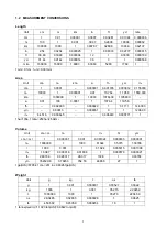
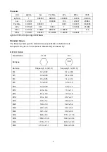
Page 8: ...76400 1195800 a 0 01 100 0 0001 1 1076 4 119 58 ft2 0 092903 0 000929 1 0 1111 144 000 yd2 0 83613 0 008361 9 1 1296 00 in2 6 4516 0 000645 0 006943 0 000771 1 1ha 100a 1mile2 259ha 2 59km2 Volume Unit cm3 cc m3 l in3 ft3 yd3 cm3 m l 1 0 000001 0 001 0 061024 0 000035 0 000001 m3 1000000 1 1000 61024 35 315 1 30796 l 1000 0 001 1 61 024 0 035315 0 001308 in3 16 387 0 000016 0 01638 1 0 000578 0 00...

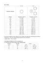
Page 9: ...wing charts give the standard torque specification of bolts and nuts Exceptions are given in the sections of Disassembly and Assembly METER TABLE Classification 4T 5T 10T Bolt type Bolt size Torque kgf m lbf ft Torque kgf m lbf ft M4 0 2 0 02 0 4 0 04 M5 0 3 0 03 0 8 0 08 M6 0 5 0 05 1 4 0 14 M8 1 2 0 12 3 3 0 3 M10 2 3 0 23 6 5 0 7 M12 4 0 0 4 11 3 1 1 M14 6 4 0 6 17 9 1 8 M16 9 5 0 9 26 7 2 7 M1...

Page 10: ...4 1 5 41 152 2 15 2 1 1 4 74 2 7 42 208 9 20 9 1 3 4 98 8 9 88 277 8 27 8 1 1 2 128 2 12 82 360 7 36 1 The torque specifications in above table shall not be applied to the bolts with nylon packings and nonferrous metal washers or the ones with specifically designated torque and standard H Newton meter 1 N m 0 1kgf m TIGHTENING TORQUE OF SPLIT FLANGE BOLTS The following torque shall be applied to t...

Page 11: ...0 069 bar megapascal MPa 145 psi 0 00689 MPa Pa N m2 Power r W J s kilowatt kW 1 36 PS cv 0 736 kW kilowatt kW 1 34 HP 0 746 kW kilowatt kW 0 948 Btu s 1 055 kW watt W 0 74 ft lb s 1 36 W W J s Energy J N m kilojoule kJ 0 948 Btu 1 055 kJ joule J 0 239 calorie 4 19 J J N m Velocity and Acceleration meter per sec2 m s2 3 28 ft s2 0 305 m s2 meter per sec m s 3 28 ft s 0 305 m s kilometer per hour k...

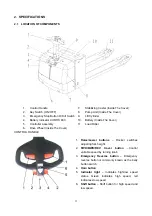
Page 12: ...roller assembly 11 Load Roller 6 Drive Wheel Inside The Cover CONTROL HANDLE 1 Raise Lower buttons Rocker switches adjusting fork height 2 FWD BWD REV travel button Control variable speed by turning knob 3 Emergency Reverse button Emergency reverse button or commonly known as the belly button switch 4 Horn button 5 Indicator light Indicates high low speed status Green indicates high speed red indi...

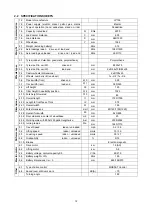
Page 13: ...rear load end b11 mm 380 525 4 4 Lift height h3 mm 120 4 9 Tiller height in neutrality position h14 mm 1323 4 15 Fork height lowered h13 mm 85 4 19 Overall length l1 mm 1725 1795 4 20 Length to front face of fork l2 mm 575 4 21 Overall width b1 mm 726 4 22 Fork dimensions s e l mm 60 160 1150 1220 4 25 Overall fork width b5 mm 540 685 4 32 Floor clearance center of wheelbase m2 mm 25 4 34 Working ...

Page 14: ...nt Cleveland open cup O C 160 160 Pour point Max O C 35 35 Density at 15 O C kg m3 861 5 Copper corrosion 100O C 3h degree 1 1 Foaming 93 5 O C ml ml 30 0 30 0 Vickers vane pump test loss of mass on vanes after 100h mg 100 15 3 Diameter of wear spot 1200 r min 294N 30min 75 O C mm 0 5 0 5 The oil for gear box Name Extreme pressure lithium based grease 1 Characteristics unit Worked Penetration 0 1m...

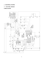
Page 15: ...14 3 ELECTRICAL SYSTEM 3 1 ELECTRICAL DIAGRAM WIRING DIAGRAM ...

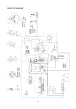
Page 16: ...15 CONNECTION DIAGRAM ...

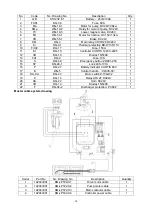
Page 17: ...IS 1243C 2405 1 12 VD DQ 10 Diodes 1N5408 1 13 FU1 DQ 9 Fuse 10A 1 14 S DQ 48 Emergency button ZDK31 250 1 15 SY DQ 26 1 Lock LKS 101A 1 16 P DQ 27 Battery Indicator CURTIS 803 1 17 B WG 5 Control handle 94300 00 1 18 SA SU DQ 23 Micro switch Z 15GW2 1 19 K DQ 14 Relay ARL2F DC24V 1 20 HA DQ 22 Horn DC24V 1 21 VD DQ 10 Diodes 1N5408 1 22 F DQ 34 2 Discharger protection PC802 1 Master cable system ...

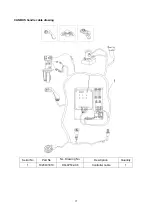
Page 18: ...17 CANBUS handle cable drawing Serial No Part No NL Drawing No Description Quantity 1 1020433019 DQ LPT22 X6 Controller cable 1 ...

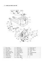
Page 19: ...25 24V 20 Washer Φ6 3 Key switch 12 Locking nut M8 21 Screw M6 30 4 Emergency button 13 Screw M10X25 22 Plug 5 Battery indicator 803 14 Elastic washer 10 23 Charger 24V 30A 6 Screw M4 25 15 Nut M10 24 Battery 7 Washer Φ4 16 Cable clip 25 Socket 8 Locking nut M4 17 screw M6X30 9 Screw M8X25 18 Screw M6X16 ...

Page 20: ...30 3 4 PUMP UNIT Type MR2 B V1B F4 5 PCMAV1Y TK05C F2 Item Specification Rated voltage 24V Rated output 0 8 kw R P M 2500 rpm Rated current 60 A Rated hour 1 8 min Insulation class F class IP Code IP54 Displacement 0 7cc rec Max operating pressure 250bar 3 5 BATTERY Rate Specification Rated voltage 24V Capacity 5 hours 210Ah Overall size L W H 677mm 196mm 555mm Initial charge When the battery is c...

Page 21: ...s of the charged battery When all the work is properly done the cells can be charged according to parameters outlined in the list below Charging current A initial charge common charge Model Phase 1 0 5 I5A Phase 2 0 25 I5A Phase 3 0 7I5A Phase 4 0 35 I5A 210Ah 21 10 5 29 14 5 280Ah 28 14 39 19 350Ah 35 17 49 24 Initial charges are conducted in 2 phases in phase1 when terminal voltages of the cells...

Page 22: ...bubbles come out convert to 1 2 of the current of phase 2 and continue to charge the cells when air bubbles are produced shut off the charge power supply keep is still for half an hour then switch on the power supply and continue to charge with 1 2 of the current of phase 2 until air bubbles are produced stop charging and left it still Repeat the procedure for several times until air bubbles are p...

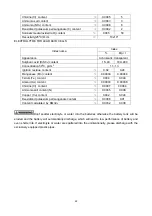
Page 23: ...nese Mn content 0 00004 0 00048 Ferrum Fe content 0 004 0 048 Arsenic As content 0 00003 0 00036 Chlorine Cl content 0 0007 0 0084 Ammonia salt content N 0 0005 0 006 Copper Cu content 0 002 0 024 Deoxidized potassium permanganate content 0 0008 0 01 Content calculated by KMn04 0 0032 0 038 Don t spatter electrolyte or water into the batteries otherwise the battery tank will be eroded and the batt...

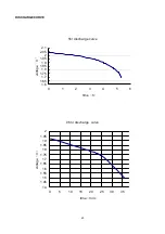
Page 24: ...E 5hr discharge curve 1 6 1 65 1 7 1 75 1 8 1 85 1 9 1 95 2 2 05 2 1 0 1 2 3 4 5 6 time h voltage V 0 5hr disvharge curve 1 4 1 45 1 5 1 55 1 6 1 65 1 7 1 75 1 8 1 85 1 9 1 95 2 0 5 10 15 20 25 30 35 time min voltage V ...

Page 25: ...l cap Do not smoke around the battery during charge Any fire and spark is forbidden MAIN PRODUCT SPECIFICATION Type Input power Battery capacity Input voltage Output voltage Output current range DF2430 1 4KVA 200 220 220v 31 2 30A ENVIRONMENTAL CONDITION No Item Technical specification Unit Remark 1 Humidity 5 80 With package 2 Altitude 2000 m Work normally 3 Cooling Fan convection cooling Working...

Page 26: ...r efficiency 3 Protection characteristics No Item Technical requirements Unit Remark 3 1 Output over voltage protection 32 V 3 2 Thermal protection When the transformer temperature is higher than 125 130 the charger automatically protect stop charging 3 3 Output current limiting protection DF2430 30 A 3 4 Output short circuit protection If a short circuit load the charger will be protected and wil...

Page 27: ... or not regularly In case of failure of microcomputer controller please inform the service engineer or maintenance staff Check height of electrolyte in the battery in accordance with the manufacturer s instructions COMMON CHARGE Connect cable plug of the battery to corresponding output plug of the charger firmly Connect the battery firstly then connect it to the power supply and finally start it I...

Page 28: ... and determine charge time manual power off and charge stop as required TROUBLESHOOTING Failures Causes Troubleshooting The indicator light for power is on the indicator light for failure is on the blower is on the charger can not start and charge and the monitor is not display The battery is not connected or the output plug of the charger is inserted into the controller plug of the electric vehic...

Page 29: ...t matching of air switch Small capacity of the air switch Rated current of the preceding stage air switch is more than that of the air switch of the charger The air switch must be type D dynamic type type C illumination type is unavailable Excessive overcharge for the battery Internal short circuit of single battery of the group Check each terminal voltage of every single battery If some of the vo...

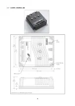
Page 30: ...29 3 7 CURTIS CONTROLLER ...

Page 31: ... is a 24 pin Molex Mini Fit Jr connector part number 39 01 2245 using type 5556 terminals Pin 1 Keyswitch input KSI Pin 2 interlok Pin 3 Not used Pin 4 Not used Pin 5 Not used Pin 6 Not used Pin 7 Not used Pin 8 Not used Pin 9 Not used Pin 10 Not used Pin 11 CAN HI Pin 12 CAN Lo Pin 13 Mode switch input Pin 14 emergency reverse Pin 15 Not used Pin 16 Output 1 horn relay Pin 17 Output 2 Pin 18 Outp...

Page 32: ...ns Appropriate screws washers and cable lugs should be used to provide secure vibration resistant connections on all power terminals The tightening torque applied to the bolts should not exceed 10 N m 7 4 ft lbs Exceeding this limit could damage the studs internal threads resulting in loose connections A 4 pin low power connector J3 is provided for the 13XX programmer A complete programmer kit inc...

Page 33: ...er User TI_UINT8 10 0 50 M2 Min Speed User User TI_UINT8 10 0 50 M3 Min Speed User User TI_UINT8 10 0 50 M4 Min Speed User User TI_UINT8 10 0 50 M1 Forward Max Speed User User TI_UINT8 50 10 100 M2 Forward Max Speed User User TI_UINT8 100 10 100 M3 Forward Max Speed User User TI_UINT8 50 10 100 M4 Forward Max Speed User User TI_UINT8 50 10 100 M1 Reverse Max Speed User User TI_UINT8 50 10 100 M2 R...

Page 34: ...INT16 10 0 100 Number of Motor Poles OEM OEM TI_UINT8 4 2 8 Encoder Pulses per Rev OEM OEM TI_UINT8 64 32 128 Swap Encoder Direction OEM OEM TI_ENUM8 0 0 1 Failsafe Delay OEM OEM Seconds TI_UINT16 5 2 20 Control User P Gain OEM OEM TI_UINT16 0 1 0 1 I Gain OEM OEM TI_UINT16 0 1 0 1 5 Accel Slip OEM OEM Hz TI_UINT16 5 1 5 Regen Slip OEM OEM Hz TI_UINT16 4 1 5 Slip Boost OEM OEM TI_UINT8 1 0 10 Pull...

Page 35: ...16 8318 0 65535 PDO MISO Index 6 OEM OEM TI_UINT16 8319 0 65535 PDO MISO Index 7 OEM OEM TI_UINT16 8320 0 65535 PDO MISO Index 8 OEM OEM TI_UINT16 8322 0 65535 PDO MISO Event Control OEM OEM TI_UINT8 0 0 2 PDO MOSI COB OEM Development TI_UINT16 517 0 65535 PDO MOSI Data Length OEM OEM TI_UINT8 8 0 8 PDO MOSI Index 1 OEM OEM TI_UINT16 8296 0 65535 PDO MOSI Index 2 OEM OEM TI_UINT16 8297 0 65535 PDO...

Page 36: ... 5 Sequencing delay too short 1 4 Static Return To Off SRO sequencing error 6 Wrong throttle type selected 1 Throttle input wire shorted to B 2 Defective throttle pot 3 Wrong throttle type selected 2 1 Throttle Wiper High Throttle wiper voltage is too high 4 Incorrect speed limit pot wiring 2 2 EMR Wiring Open Emergency reverse wiring fault 1 Emerg Rev wire or check wire broken 1 Improper sequence...

Page 37: ...cessive load on vehicle 3 Improper mounting of controller 4 3 Temperature Cutback Controller heatsink is too hot or too cold 4 Operation in extreme environment 1 Mode switch shorted to B 4 4 Anti Tiedown Mode switch activated at startup 2 Mode switch tied down to select M2 permanently 5 1 Hardware Failure Hardware failure 1 Controller defective 5 2 Software Failure Software failure 1 Controller de...

Page 38: ...on quickly press the appropriate bookmark key 1 2 or 3 Note that the bookmarks are not permanently stored in the programmer They are cleared when the programmer is unplugged The bookmark keys can be used to make parameter adjustment easier For example in adjusting the throttle deadband you might set a bookmark at the Throttle readout Monitor THROTTLE and another at the Throttle Deadband parameter ...

Page 39: ...affected by Pin 2 although it cannot accumulate more time as long as the keyswitch pin is not energized The control inputs HRM and HRM are enabled by the keyswitch Pin 2 is connected to the vehicle s keyswitch Pins 1 6 Hour Meter Control In normal operation Pin 1 or 6 is connected and the other is left open Only one of these pins is connected when using normal hour meter function It is possible to...

Page 40: ...89 1 91 1 93 NOTE factory setting RESET TYPE LEVEL AFTER OR DURING RECHARGE CTR Charge Tracking Reset If the gage is connected to the battery during recharge the gage will track the battery charge level OCR Open Circuit Reset If the gage is disconnected from the battery during recharge the gage will retain the last indication It will advance to full when reconnected only if the battery voltage is ...

Page 41: ...Step 2 Remove the battery cover No 1 Step 3 Separate the plugs No 6 and 7 Step 4 Use two lifting hook to hook the hole of the battery box Then you can use a crane to take away the battery and replace it REPLACING THE CONTROLLER BATTERY INDICATOR ETC Remove screws Then remove the right cover and left cover You will see the appearance as the following three pictures when you remove the cover ...

Page 42: ... Remove 2 screws Then you can remove the power unit and replace it REPLACING THE BATTERY INDICATOR Remove two plastic nuts under the mounting board remove the U clamp disconnect the 8 pins plug Then you can remove the battery indicator and replace it REPLACINGTHE FUSE ...

Page 43: ...3 then you can remove the controller and replace it When reconnecting the controller be careful to check the tightness of the power connection nut Be sure to check the terminal connections Taking part A and B for example part A It includes anode terminal and cathode terminal if you connect by mistake the circuit will be short out and the controller will be damaged Part B there are three terminals ...

Page 44: ... 110O C the unit will change back to nomal speed If one line of the cable open circuit the driving speed will remain slow Remove the screw and the plug then you can remove the module and replace it REPLACING THE LOCK KEY SWITCH LKS 101A Remove four screws that fix the plate into vehcle frame Lift the mounting plate Remove the nut of the key switch remove the cable of the key switch Then you can re...

Page 45: ...f the mandril and the groove of the sleeve be in the same line Insert the hole with a small screwdriver then turn counter clockwise the mushroom head to remove it Remove two screws Take out the emergency button remove two bolts and then remove the cable then you can remove the emergency button and replace it ...

Page 46: ... Figure Application 1 Tool for removal of pins sleeves 2 Tool for application of pins sleeves 3 Tool for release of lock 4 Tool for application of secondary locking 2 pole 5 Tool for application of secondary locking 4 pole 6 Tool for removal of pins sleeves ...

Page 47: ...ar but the color becames bright Fine Mixed with other oil Inspect the viscosity and if fine it can be continuously used Color changed like milk Fine Mixed with air and water Separate water or replace oil Color changed into dark brown Bad Oxidized Replace oil Clear but there are small black spots Fine Mixed with other particles Use after filtering 4 2 INSTALLATION OF HYDRAULIC SYSTEM ...

Page 48: ...lve 4 Holding bracket 10 Rubber oil pipe 16 Oil tank 5 cylinder 11 bolt 17 Bush 6 Bolt 12 Combination washer 18 4 3 REPLACING THE POWER UNIT Remove the relay cable Remove the pipe Remove 2 screws Then you can remove the power unit and replace it Collapse the forks to the loweredd position Then drain the hydraulic oil from the power unit ...

Page 49: ...INDER Disconnect two bolts and the other bolts in the other side Remove two screws Remove the oil pipe Remove two elastic washers Remove the shaft which pass through the cylinder then you can remove the cylinder and replace it ...

Page 50: ...wo screws markd B then you can separate the power unit into the motor No 1 the mounting plate of vavle No 4 the suction filter No 12 the oil tank No 13 Clean up the mounting plate for valve No 4 etc Clean up the filter by compressed air then inspect to check if the filter is blocked or damaged And If the filter is blocked or damaged it need be replaced Cleaning up the oil tank remove dust or forei...

Page 51: ...ing oil is ventilate When lower the air will come out from the tank it might take out little oil vapour So it might appear phenomena that a little oil stains on the plug after some time This aphenomena is not caused by leaking Because the electric current of the Relay for the lifting motor is very big and work continually hourly the contact terminal of the relay is easy damaged Please check it con...

Page 52: ...51 HYDRAULIC PIPE For shocking the joint of the hydraulic pipe and hydraulic pipe might be loosed and leak oil so usually check it and tighten it ...

Page 53: ... DRIVE WHEEL No Part name No Part name 1 Bolt 9 Bolt 2 Brake 10 Upper cover 3 Bolt 11 Seal washer 4 Tiller bar plate 12 Bolt 5 Motor 13 Wheel 6 Bolt 14 Bolt for adding oil 7 Gear 15 Gear box 8 Holding bearing ...

Page 54: ...picture Step4 Loosen the screws marked A as the right picture Step5 Remove all the cables that fixed in the motor Step6 Hoist the vehicle through the hole marked 4 as bove picture Step7 Then you can remove the drive motor from chassis and replace it Or you can directly replace the wheel Cut off the power before operating Remove 5 nuts with the spanner Then you can remove the drive wheel and replac...

Page 55: ...ake coil must always be connected to the power 24v when energized the brake will dis engage If the brake system loose power while unit is use the unit may lose speed and motor may reduce excessive heat Step 1 Measure the resistance by multimeter 200Ω and The Winding resistance 25Ωnormal 1 1 Ω Step 2 Loosen the three bolts that hold the brake ...

Page 56: ...st the Clearance of the brake plate Be sure not to over tighten the bolts Step 4 Adjust the above mentioned bolts counter clockwise adjust 2 3 revolutions to reduce the spring tension Ensure brake disk is clean free of dust Also ensure the plug is firmly connected ...

Page 57: ...1 Bushing 23 19 17 10 8 Air spring 2 Handle mounting bracket 9 Handle cable 3 Shaft 17 10 Micro switch Z 15GW2 4 Roll pin 4x24 11 Screw M4x25 5 Socket hex bolts M8x25 12 Cover 6 Elastic washer 8 13 Screw M4x10 7 Socket hexa bolts M8X16 14 Tillerarm ...

Page 58: ... Screw M6X10 22 Seesaw right or toggle button right 8 Socket hexagonal Screw M3X16 23 Tapping screw ST4 2X25 9 Washer 3 24 LED bicolor 10 Butterfly right 25 Housing for LED two parts 11 Edge Shaft 26 Spring RH throttle torsion 12 PCB clip 27 Spring LH throttle torsion 13 Sensor for rocker lever 28 Printed board 14 Upper part 15 Lower part 6 1 REPLACING THE CONTROL HANDLE Remove 3 bolts which are b...

Page 59: ... removed from the throttle lever the opposing throttle lever and throttle shaft can be pulled out through the oppsoing side of the handle Once the throttle levers are removed the PCB power control board can be removed When inspection the PCB ensure the micro switch rocker lever And the plug connections are firmly connected to the cirsuit board and are servicable ...

Page 60: ...ro Switch and Air Spring Ensure the micro switch is mounted in the correct position The switch may require adjustment upon re installation Use a Phillps screwdriver to remove two screws then you can dismantle the air spring and replace it Remove this bolt Then you can remove the micro switch and replace it ...

Page 61: ...aantle the caster and replace it 7 2 ADJUSTING THE PRESSURE FOR THE DRIVE WHEEL After using some time the drive wheel might wear off the pressure for the drive wheel will not be enough and drive wheel can not bit into the ground and slip You can adjust it according to following steps Step 1 Loose the four bolts do not need to dismantle them Step 2 Take away one or two piece washer ...

Page 62: ... performance 8 2 Inspection of safety and reliability of connection of all cables and if any damage 8 3 Inspection of Amperage of fuse 8 4 Inspection of safety reliability and function of switches and unlocking cam equipment 8 5 Inspection of connector replace the worn part if necessary Electrical system 8 6 Inspection of function of alarm equipment 9 1 Inspection of wearing state of carbon brush ...

Page 63: ...62 8 2 TROUBLE SHOOT ...

Page 64: ...63 ...

Page 65: ...64 ...

Reviews:

Related manuals for LPT22