31
A 6-pin low power Molex connector (J2) is provided for the speed encoder and electromagnetic brake
connections. The mating connector is a Molex Mini-FitJr. p/n 39-01-2065 using type 5556 terminals.
Note: In some applications using a tiller multiplexer, J2 Pins 3 and 6 are used for a proportional valve
instead of an electromagnetic brake.
High Current Connections
Six round tin-plated brass studs are provided for the high current connections to the battery (B+ and B-),
the fuse (F+), and the three motor phases (U, V, W), located as shown in Figure 2.
The studs are threaded to accept M5 bolts. This simplifies the assembly and reduces the mounting
hardware necessary for the power connections. Appropriate screws, washers, and cable lugs should be
used to provide secure vibration-resistant connections on all power terminals.
The tightening torque applied to the bolts should not exceed 10 N·m (7.4 ft-lbs). Exceeding this limit
could damage the studs’ internal threads, resulting in loose connections.
A 4-pin low power connector (J3) is provided for the 13XX
programmer. A complete programmer kit, including the
appropriate connecting cable, can be ordered; see Curtis
programmer manual for further information on the various
programmers available for programming Curtis controllers.
J3 can also be used for the Curtis Model 840 Spyglass display.
Although the display is typically wired directly into Pins 19, 20,
and 21 of the 24-pin connector (J1), it can alternatively be
plugged into J3 and unplugged when the programmer is used.
Only Pins 2, 3, and 4 of J3 are needed for the display.
Summary of Contents for LPT22
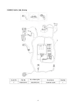
Page 15: ...14 3 ELECTRICAL SYSTEM 3 1 ELECTRICAL DIAGRAM WIRING DIAGRAM ...
Page 16: ...15 CONNECTION DIAGRAM ...
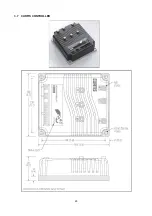
Page 30: ...29 3 7 CURTIS CONTROLLER ...
Page 63: ...62 8 2 TROUBLE SHOOT ...
Page 64: ...63 ...
Page 65: ...64 ...

