background image

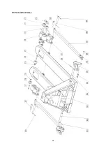
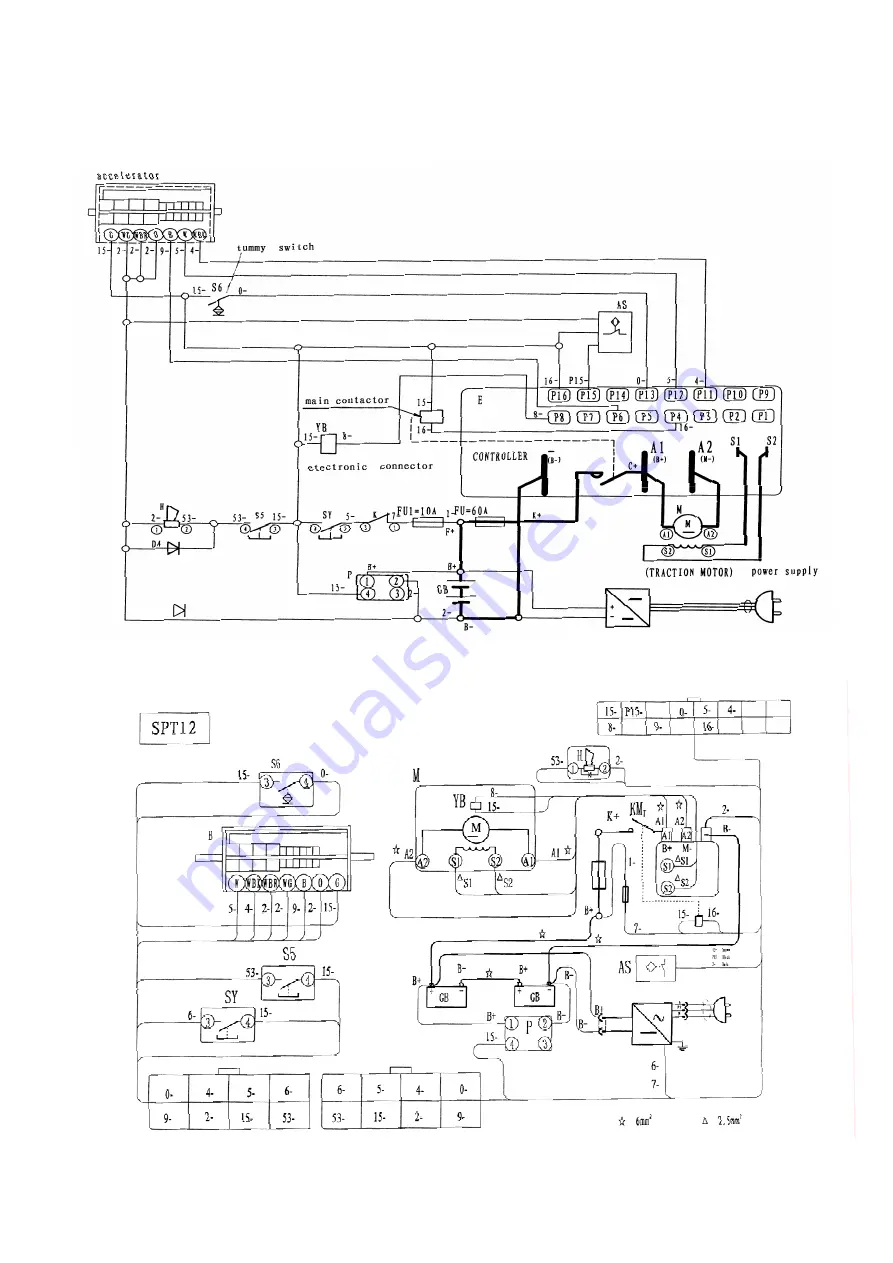
7  ELECTRICAL DIAGRAMS 

7.1 CIRCUIT DIAGRAM 


7.2 CONNECTION DIAGRAM


18

Summary of Contents for SPT15 Series

Page 1: ...stacker before reading and understanding this operating instructions NOTE Keep for future reference Chinese well known trademark National inspection exempted product Operating Instructions Parts List...

Page 2: ...t you have to pay attention before operation The majority of materials that consists of the equipment can be completely recycled During the working repairing maintenance and cleaning there are some wa...

Page 3: ...training and specific authorization the operator is forbidden to repair or change any part of the pallet truck Any change of installation position of switches and safety devices is strictly forbidden...

Page 4: ...gers simultaneously passengers must enter the elevator after the pallet truck and walk out of the elevator before the pallet truck The total weights weight of vehicle weights of goods 1 10 Operation m...

Page 5: ...slope or the inclined plane The forks must be lowered to the lowest position after working so no accident occurring when the fork dropping suddenness 1 14 Signaling for warning You should use the tru...

Page 6: ...ne 3 2 Tyre size drive end mm 220 70 3 3 Tyre size load end mm 80 70 3 4 Castor wheels dimensions mm 50 30 Wheels types 3 5 Wheels number x drive wheel drive end load end 1x 2 4 4 2 Overall height h m...

Page 7: ...confirms that the vehicle meets the requirement of the limit values for electromagnetic emission and interference immunity according to EN12895 and the related standards contained therein the testing...

Page 8: ...of fittings such as a bored shaft two elastic pin remarks the one of the two have already assembled on the bored shaft these two fittings have been put into a plastic bag the bag has been bound to th...

Page 9: ...rol handle 217 which can be adjusted in three positions Raise handle down Drive handle in center position Lower handle up the lever moves back the drive position when released If however they have bee...

Page 10: ...fferent wire in a clear and tidy condition fastening it so until now the work is done 3 5 Battery assembling demount the shields of charger and battery in sequence by screwdriver moving the battery to...

Page 11: ...of the control circuit 4 2 Starting up of Truck The operator must confirm no persons staying in the danger area before starting and operating the truck or lifting cargos Routine Checking before Starti...

Page 12: ...he truck is moving towards the selected direction Driving Swing the FWD BWD Tuning Knob leftwards or rightwards to drive Driving on a Slope The cargo carried must face to upward direction of the slope...

Page 13: ...position of the FWD BWD Tuning Knob If inertia braking is removed by maintenance staff and the FWD BWD Tuning Knob is set at 0 position the truck can be stopped only by electromagnetic braking and re...

Page 14: ...2 The connecting lines between cells should be in good contact Check nuts if loosening or sliding If so fasten it 3 Keep the surface of the battery clean and dry 4 Over charge and over discharge shou...

Page 15: ...asations should be eliminated through neutralization treatment 5 2 Type of Battery The weight and the dimension of the battery can be known from the battery nameplate During replacement or assembly of...

Page 16: ...attery charger is built in automatically operation and intellectual ability You only need to connect between charger and electric power the charger will automatically adjust the volume of current acco...

Page 17: ...move the draw bar up and down for several times 6 1 3Lubrication before delivery all of the bearings and shaft pole have been placed with enduring lubrication oil so you need maintain it with lubricat...

Page 18: ...is in the wrong position Replace big piston rod 118 or oil pump body 112 lower the fork to the lowest position and lubricating the piston rod in time Repeat adjust nut 207 or screw 111 refer to 3 3 4...

Page 19: ...7 ELECTRICAL DIAGRAMS 7 1 CIRCUIT DIAGRAM 7 2 CONNECTION DIAGRAM 18...

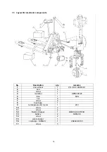
Page 20: ...4KW 24V 2 bolt 4 3 screw 1 4 contactor 1 HZBD 80 24 5 fuse 1 60A 6 nut 2 7 screw 2 8 fuse base 1 9 rectangle electric meter 1 24V 10 screw 2 11 screw 4 12 Built in charger 1 QQE192 4CH12 B 13 battery...

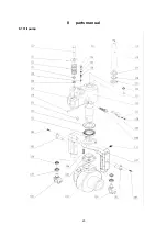
Page 21: ...8 parts manual 8 1 Oil pump 20...

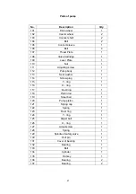
Page 22: ...1 112 Pump body 1 113 Seal washer 1 114 Screw plug 1 115 Y ring 1 116 O ring 1 117 Dust ring 1 118 Piston rod 1 119 Steel ball 1 120 Pump piston 1 121 Spring cap 1 122 Spring 1 123 Dust ring 1 124 Y r...

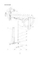
Page 23: ...8 2 Parts of handle 22...

Page 24: ...knut 1 208 Adjust bolt 1 209 Chain 1 210 Release Rod 1 211 Handle 1 212 Screw 4 213 Screw 4 214 Cover 1 215 Steel ball 1 216 Spring sleeve 1 217 Control handle 1 218 Spring 1 219 Steel ball 1 220 Pin...

Page 25: ...8 3 Parts of fork frame 24...

Page 26: ...haft 2 309 Roll pin 4 310 Roll pin 2 311 Frame of Roller 2 312 Linking Plate 4 313 Bearing 8 314 Roll pin 8 315 Shaft for roller 4 316 Load roller 4 317 Bolt 2 318 Enter Roller 2 319 Nut 2 320 Shaft6...

Reviews: