


eBOX
‐
3220
User
Manual
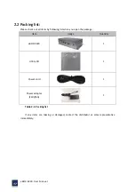
26
Figure
2
‐
16:
VGA
connection
Step
4:
Secure
the
VGA
connector.
Secure
the
DB
‐
15
VGA
connector
from
the
VGA
monitor
to
the
external
interface
by
tightening
the
two
retention
screws
on
either
side
of
the
connector.
2.7.5
HDMI
connector
The
HDMI
output
can
be
connected
to
an
external
HDMI
monitor.
To
connect
the
HDMI
monitor
to
the
eBOX
‐
3220,
please
follow
the
instruction
below:
Step
1:
Located
the
HDMI
connectors.
The
locations
of
the
HDMI
connectors
are
shown
above.
Step
2:
Align
the
connectors.
Align
connector
on
HDMI
screen
cable
with
the
connector
on
the
external
peripheral
interface.
Step
3:
Insert
the
HDMI
connector.
Once
the
connectors
are
properly
aligned
with
the
insert
the
connector
from
the
HDMI
screen
into
HDMI
connector
on
the
eBOX
‐
3220,
please
see
the
figure
2
‐
16:
Step
4:
Secure
the
HDMI
connector.
Secure
the
HDMI
connector
from
the
HDMI
monitor
to
the
external
interface
by
tightening
the
two
retention
screws
on
either
side
of
the
connector.
2.8
Power
connector
The
power
cable
connects
the
panel
PC
to
power
supply.
The
power
cable
is
required
for
operation
of
the
panel
PC.
Step
1:
Connect
one
end
to
the
panel
PC.
Step
2:
Connect
the
other
end
to
the
included
power
supply.
Summary of Contents for eBOX-3220
Page 1: ...eBOX 3220 User Manual 1 User ManualVer1 0 eBOX 3220 Industrial Box PC ...
Page 8: ...eBOX 3220 User Manual 8 Chapter 1 OVERVIEW ...
Page 14: ...eBOX 3220 User Manual 14 1 6 Dimensions Figure 1 5 eBOX 3220 dimension ...
Page 15: ...eBOX 3220 User Manual 15 Chapter 2 INSTALLATIONS ...
Page 32: ...eBOX 3220 User Manual 32 Press YES to agree the License agreement then go to the next step ...
Page 38: ...eBOX 3220 User Manual 38 Press YES to agree the License agreement then go to the next step ...
Page 40: ...eBOX 3220 User Manual 40 Press YES to continue ...
Page 43: ...eBOX 3220 User Manual 43 Press NEXT to continue ...
Page 45: ...eBOX 3220 User Manual 45 ...
Page 51: ...eBOX 3220 User Manual 51 Chapter 3 BIOS Setup ...
Page 55: ...eBOX 3220 User Manual 55 Figure 3 2 Advanced BIOS Features Setup Screen 3 3 1 ACPI Setting ...
Page 56: ...eBOX 3220 User Manual 56 Figure 3 4 ACPI Configuration Setting ...
Page 57: ...eBOX 3220 User Manual 57 3 3 2 CPU Configuration Setting ...
Page 58: ...eBOX 3220 User Manual 58 ...
Page 59: ...eBOX 3220 User Manual 59 ...
Page 61: ...eBOX 3220 User Manual 61 3 3 3 SATA Configuration Figure 3 6 SATAconfiguration ...
Page 63: ...eBOX 3220 User Manual 63 Figure 3 7 USB Configuration ...
Page 64: ...eBOX 3220 User Manual 64 3 3 5 Super I O Configuration ...
Page 65: ...eBOX 3220 User Manual 65 ...
Page 66: ...eBOX 3220 User Manual 66 ...
Page 67: ...eBOX 3220 User Manual 67 Figure 3 8Super I O configuration Device settings ...
Page 69: ...eBOX 3220 User Manual 69 3 3 7 Displayconfiguration ...
Page 70: ...eBOX 3220 User Manual 70 ...
Page 72: ...eBOX 3220 User Manual 72 3 3 8 Restore AC Power LOSS Configuration ...
Page 74: ...eBOX 3220 User Manual 74 3 4 Chipset Settings North Bridge Figure 3 11 Chipset north Settings ...
Page 75: ...eBOX 3220 User Manual 75 3 5 Chipset settings south bridge ...
Page 78: ...eBOX 3220 User Manual 78 ...
Page 79: ...eBOX 3220 User Manual 79 ...
Page 80: ...eBOX 3220 User Manual 80 3 6 Exit Option Figure 3 17 Exit Option ...
Page 82: ...eBOX 3220 User Manual 82 Chapter 4 System Maintenance ...
Page 84: ...eBOX 3220 User Manual 84 Figure 4 1 Back cover retention screws ...
Page 85: ...eBOX 3220 User Manual 85 A Safety Precautions ...
Page 89: ...eBOX 3220 User Manual 89 B ALC662 Digital Microphone Configuration ...
Page 94: ...eBOX 3220 User Manual 94 C Watchdog Timer ...
Page 97: ...eBOX 3220 User Manual 97 D Hazardous Materials Disclosure ...
Page 100: ...eBOX 3220 User Manual 100 ...


