


eBOX
‐
3220
User
Manual
27
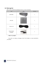
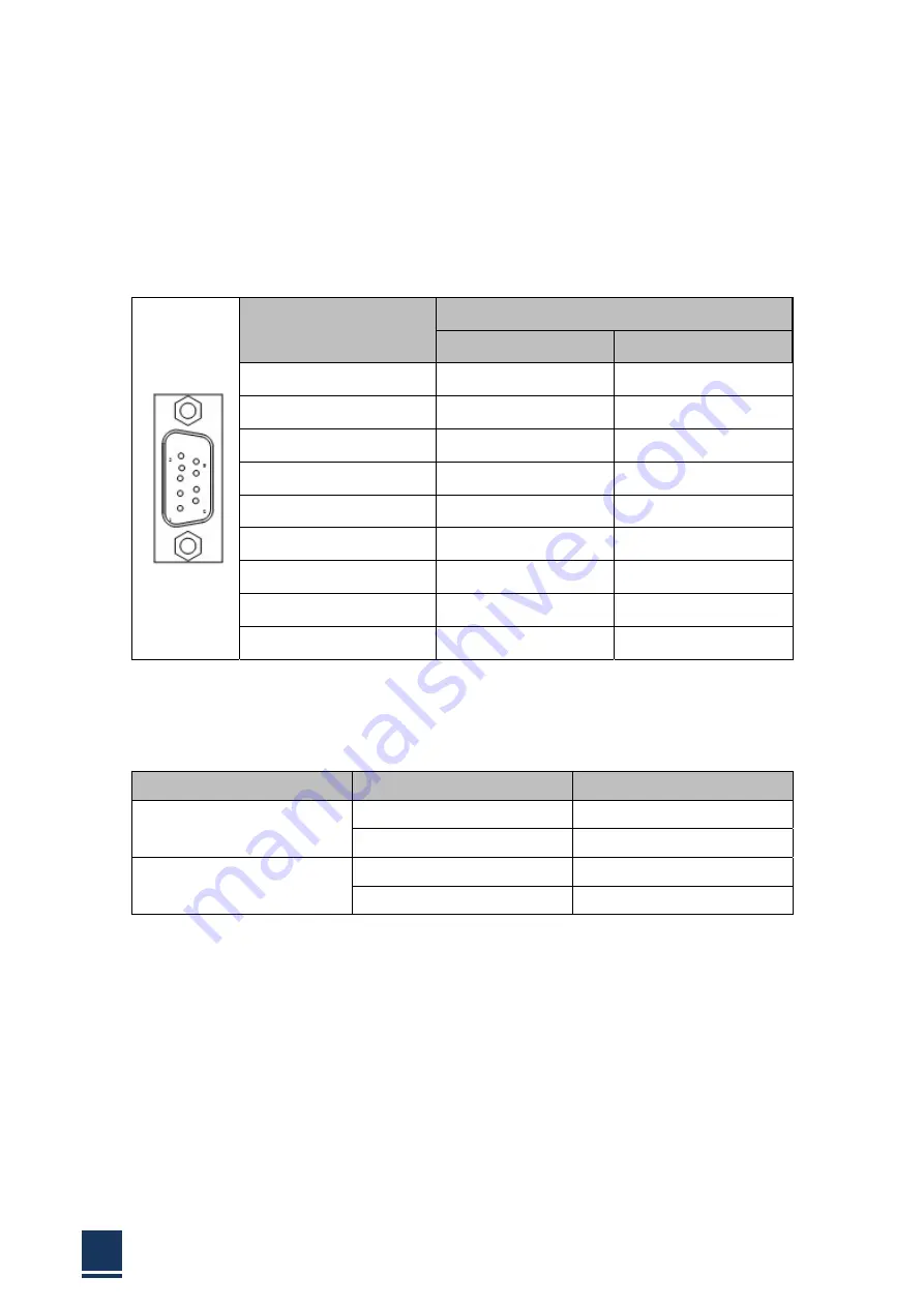
2.9
Connectors
Definition
COM
port
COM1~4
are
DB9
connector
and
its
definition
is:
Table
2
‐
2:
COM1~4
DB9
connector
PIN9
on
DB9
defaults
RI,
you
can
set
to
5V
or
12V
by
jumpers
here
is
the
definitions:
Jumper
Settings
Function
JC_1
1
‐
3,
2
‐
4
(Default)
COM1
RS
‐
232
3
‐
5,
4
‐
6
COM1
RS
‐
485
J1
1
‐
3,
2
‐
4
(Default)
COM1
RS
‐
232
3
‐
5,
4
‐
6
COM1
RS
‐
485
Table
2
‐
3:
Jumper
of
PIN9
on
DB9
USB
We
provide
a
standard
single
deck
USB
port
in
front
panel
and
2
x
2
standard
double
‐
deck
USB
interface
on
I/O
interfaces,
you
can
use
the
5
USB
interfaces
at
the
same
time,
and
here
is
the
interface
definition:
PIN
SIGNAL
RS
‐
232
RS
‐
485
1
DCD
Data
‐
2
RXD
Data+
3
TXD
N/A
4
DTR
N/A
5
GND
GND
6
DSR
N/A
7
RTS
N/A
8
CTS
N/A
9
RI
N/A
Summary of Contents for eBOX-3220
Page 1: ...eBOX 3220 User Manual 1 User ManualVer1 0 eBOX 3220 Industrial Box PC ...
Page 8: ...eBOX 3220 User Manual 8 Chapter 1 OVERVIEW ...
Page 14: ...eBOX 3220 User Manual 14 1 6 Dimensions Figure 1 5 eBOX 3220 dimension ...
Page 15: ...eBOX 3220 User Manual 15 Chapter 2 INSTALLATIONS ...
Page 32: ...eBOX 3220 User Manual 32 Press YES to agree the License agreement then go to the next step ...
Page 38: ...eBOX 3220 User Manual 38 Press YES to agree the License agreement then go to the next step ...
Page 40: ...eBOX 3220 User Manual 40 Press YES to continue ...
Page 43: ...eBOX 3220 User Manual 43 Press NEXT to continue ...
Page 45: ...eBOX 3220 User Manual 45 ...
Page 51: ...eBOX 3220 User Manual 51 Chapter 3 BIOS Setup ...
Page 55: ...eBOX 3220 User Manual 55 Figure 3 2 Advanced BIOS Features Setup Screen 3 3 1 ACPI Setting ...
Page 56: ...eBOX 3220 User Manual 56 Figure 3 4 ACPI Configuration Setting ...
Page 57: ...eBOX 3220 User Manual 57 3 3 2 CPU Configuration Setting ...
Page 58: ...eBOX 3220 User Manual 58 ...
Page 59: ...eBOX 3220 User Manual 59 ...
Page 61: ...eBOX 3220 User Manual 61 3 3 3 SATA Configuration Figure 3 6 SATAconfiguration ...
Page 63: ...eBOX 3220 User Manual 63 Figure 3 7 USB Configuration ...
Page 64: ...eBOX 3220 User Manual 64 3 3 5 Super I O Configuration ...
Page 65: ...eBOX 3220 User Manual 65 ...
Page 66: ...eBOX 3220 User Manual 66 ...
Page 67: ...eBOX 3220 User Manual 67 Figure 3 8Super I O configuration Device settings ...
Page 69: ...eBOX 3220 User Manual 69 3 3 7 Displayconfiguration ...
Page 70: ...eBOX 3220 User Manual 70 ...
Page 72: ...eBOX 3220 User Manual 72 3 3 8 Restore AC Power LOSS Configuration ...
Page 74: ...eBOX 3220 User Manual 74 3 4 Chipset Settings North Bridge Figure 3 11 Chipset north Settings ...
Page 75: ...eBOX 3220 User Manual 75 3 5 Chipset settings south bridge ...
Page 78: ...eBOX 3220 User Manual 78 ...
Page 79: ...eBOX 3220 User Manual 79 ...
Page 80: ...eBOX 3220 User Manual 80 3 6 Exit Option Figure 3 17 Exit Option ...
Page 82: ...eBOX 3220 User Manual 82 Chapter 4 System Maintenance ...
Page 84: ...eBOX 3220 User Manual 84 Figure 4 1 Back cover retention screws ...
Page 85: ...eBOX 3220 User Manual 85 A Safety Precautions ...
Page 89: ...eBOX 3220 User Manual 89 B ALC662 Digital Microphone Configuration ...
Page 94: ...eBOX 3220 User Manual 94 C Watchdog Timer ...
Page 97: ...eBOX 3220 User Manual 97 D Hazardous Materials Disclosure ...
Page 100: ...eBOX 3220 User Manual 100 ...


