


eBOX
‐
3220
User
Manual
83
4.1
System
Maintenance
Introduction
If
the
components
of
the
eBOX
‐
3220
fail
they
must
be
replaced,
such
as
the
wireless
LAN
module
or
the
motherboard.
Please
contact
the
system
reseller
or
vendor
to
purchase
the
replacement
parts.
Back
cover
removal
instructions
and
jumper
settings
for
the
eBOX
‐
3220
are
described
below.
4.2
Motherboard
Replacement
In
the
case
of
motherboard
failure,
please
contact
an
IEI
sales
representative,
reseller
orsystem
vendor.
The
motherboard
is
accessible
after
opening
the
rear
cover.
4.3
Cover
Removal
Warning:
Turn
off
the
power
before
removing
the
back
cover
.
Risk
of
electrocution.
Severe
damage
to
the
product
and
injury
to
the
body
may
occur
if
internal
parts
are
touched
while
the
power
is
still
on.
Warning:
Take
antistatic
precautions
when
working
on
the
internal
components.
Some
internal
components
are
easily
damaged
or
destroyed
by
electrostatic
discharge.
Take
antistatic
precautions
to
prevent
electrostatic
discharge.
To
replace
any
of
the
following
components,
Memory
module
Wireless
LAN
module
Inverter
The
back
cover
of
the
eBOX
‐
3220
must
be
removed.
To
remove
the
back
cover,
loosen
the
four
silver
screws,
slide
the
cover
down
and
then
lift
to
remove.
Summary of Contents for eBOX-3220
Page 1: ...eBOX 3220 User Manual 1 User ManualVer1 0 eBOX 3220 Industrial Box PC ...
Page 8: ...eBOX 3220 User Manual 8 Chapter 1 OVERVIEW ...
Page 14: ...eBOX 3220 User Manual 14 1 6 Dimensions Figure 1 5 eBOX 3220 dimension ...
Page 15: ...eBOX 3220 User Manual 15 Chapter 2 INSTALLATIONS ...
Page 32: ...eBOX 3220 User Manual 32 Press YES to agree the License agreement then go to the next step ...
Page 38: ...eBOX 3220 User Manual 38 Press YES to agree the License agreement then go to the next step ...
Page 40: ...eBOX 3220 User Manual 40 Press YES to continue ...
Page 43: ...eBOX 3220 User Manual 43 Press NEXT to continue ...
Page 45: ...eBOX 3220 User Manual 45 ...
Page 51: ...eBOX 3220 User Manual 51 Chapter 3 BIOS Setup ...
Page 55: ...eBOX 3220 User Manual 55 Figure 3 2 Advanced BIOS Features Setup Screen 3 3 1 ACPI Setting ...
Page 56: ...eBOX 3220 User Manual 56 Figure 3 4 ACPI Configuration Setting ...
Page 57: ...eBOX 3220 User Manual 57 3 3 2 CPU Configuration Setting ...
Page 58: ...eBOX 3220 User Manual 58 ...
Page 59: ...eBOX 3220 User Manual 59 ...
Page 61: ...eBOX 3220 User Manual 61 3 3 3 SATA Configuration Figure 3 6 SATAconfiguration ...
Page 63: ...eBOX 3220 User Manual 63 Figure 3 7 USB Configuration ...
Page 64: ...eBOX 3220 User Manual 64 3 3 5 Super I O Configuration ...
Page 65: ...eBOX 3220 User Manual 65 ...
Page 66: ...eBOX 3220 User Manual 66 ...
Page 67: ...eBOX 3220 User Manual 67 Figure 3 8Super I O configuration Device settings ...
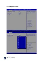
Page 69: ...eBOX 3220 User Manual 69 3 3 7 Displayconfiguration ...
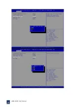
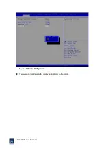
Page 70: ...eBOX 3220 User Manual 70 ...
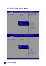
Page 72: ...eBOX 3220 User Manual 72 3 3 8 Restore AC Power LOSS Configuration ...
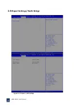
Page 74: ...eBOX 3220 User Manual 74 3 4 Chipset Settings North Bridge Figure 3 11 Chipset north Settings ...
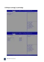
Page 75: ...eBOX 3220 User Manual 75 3 5 Chipset settings south bridge ...
Page 78: ...eBOX 3220 User Manual 78 ...
Page 79: ...eBOX 3220 User Manual 79 ...
Page 80: ...eBOX 3220 User Manual 80 3 6 Exit Option Figure 3 17 Exit Option ...
Page 82: ...eBOX 3220 User Manual 82 Chapter 4 System Maintenance ...
Page 84: ...eBOX 3220 User Manual 84 Figure 4 1 Back cover retention screws ...
Page 85: ...eBOX 3220 User Manual 85 A Safety Precautions ...
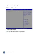
Page 89: ...eBOX 3220 User Manual 89 B ALC662 Digital Microphone Configuration ...
Page 94: ...eBOX 3220 User Manual 94 C Watchdog Timer ...
Page 97: ...eBOX 3220 User Manual 97 D Hazardous Materials Disclosure ...
Page 100: ...eBOX 3220 User Manual 100 ...


