4
Installing and Replacing Optional Cards
56
Nokia 100i Installation Guide
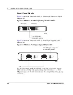
Front Panel Details
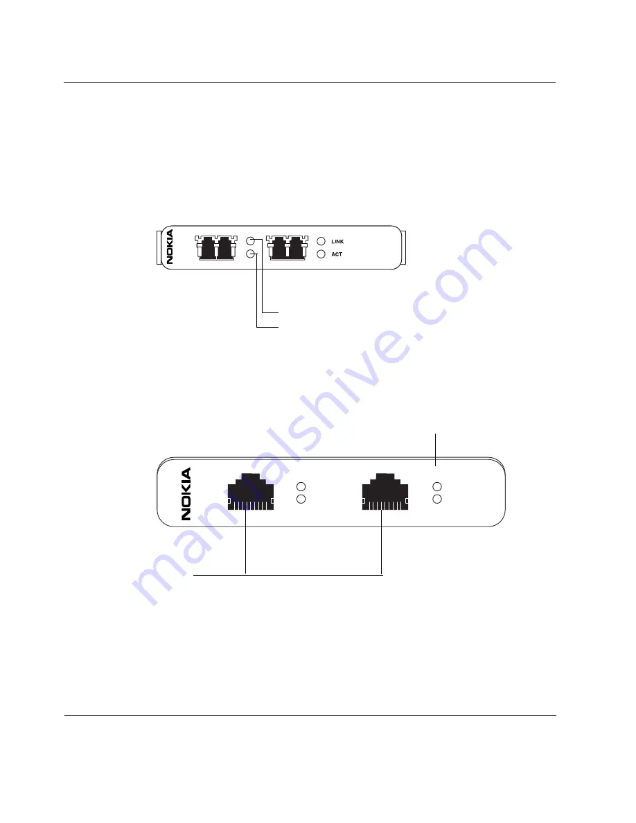
Figure 13
shows the front panel details for the dual-port fiber optic Gigabit
Ethernet NIC.
Figure 13 PMC Dual-Port Fiber Optic Gigabit Ethernet NIC
Figure 14
shows the front panel details for the dual-port copper Gigabit
Ethernet NIC.
Figure 14 PMC Dual-Port Copper Gigabit Ethernet NIC
For the PMC format cards, the link LED on the NIC is bicolored. A green
LED indicates a 1 Gbps link speed, and a yellow LED indicates a 10/100
Mbps link speed. As the NIC transmits data, the activity LEDs on the gateway
illuminate.
00239b
GIGE
Port 1 (P1)
Port 2 (P2)
Link LED (green)
Activity LED (yellow)
GIG E
1
LINK
ACT
LINK
ACT
2
00386.2
Ports
Link LEDs (green or yellow)
Activity LEDs (yellow)
Summary of Contents for 100i
Page 1: ...Nokia100i Installation Guide Part No N451654001 Rev A Published June 2005 ...
Page 4: ...4 Nokia 100i Installation Guide ...
Page 8: ...8 Nokia 100i Installation Guide ...
Page 22: ...1 Overview 22 Nokia 100i Installation Guide ...
Page 26: ...2 Installing the Gateway 26 Nokia 100i Installation Guide ...
Page 58: ...4 Installing and Replacing Optional Cards 58 Nokia 100i Installation Guide ...
Page 62: ...5 Troubleshooting 62 Nokia 100i Installation Guide ...
Page 70: ...B Compliance Information 70 Nokia 100i Installation Guide ...

