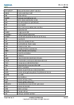
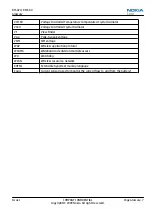
background image

Glossary

Nokia Customer Care

Issue 1

COMPANY CONFIDENTIAL

Page Glossary–1

Copyright © 2009 Nokia. All rights reserved.

Summary of Contents for 6720 classic

Page 1: ...Service Manual RM 424 RM 564 Nokia 6720 classic L3 4 Mobile Terminal Part No Issue 1 Nokia Customer Care COMPANY CONFIDENTIAL Copyright 2009 Nokia All rights reserved ...

Page 2: ...Amendment Record Sheet Amendment No Date Inserted By Comments Issue 1 04 2009 MT RM 424 RM 564 Amendment Record Sheet Page ii COMPANY CONFIDENTIAL Issue 1 Copyright 2009 Nokia All rights reserved ...

Page 3: ...er no circumstances shall Nokia be responsible for any loss of data or income or any special incidental consequential or indirect damages howsoever caused The contents of this document are provided as is Except as required by applicable law no warranties of any kind either express or implied including but not limited to the implied warranties of merchantability and fitness for a particular purpose...

Page 4: ...CONNECTIONS MAKE SURE YOU HAVE SWITCHED OFF ALL EQUIPMENT Cautions Servicing and alignment must be undertaken by qualified personnel only Ensure all work is carried out at an anti static workstation and that an anti static wrist strap is worn Ensure solder wire or foreign matter does not enter the telephone as damage may result Use only approved components as specified in the parts list Ensure all...

Page 5: ...approved accessories and batteries Do not connect incompatible products CONNECTING TO OTHER DEVICES When connecting to any other device read its user s guide for detailed safety instructions Do not connect incompatible products RM 424 RM 564 For your safety Issue 1 COMPANY CONFIDENTIAL Page v Copyright 2009 Nokia All rights reserved ...

Page 6: ...e damaged by static electricity discharge All ESD sensitive parts must be packed in metallized protective bags during shipping and handling outside any ESD Protected Area EPA Every repair action involving opening the product or handling the product components must be done under ESD protection ESD protected spare part packages MUST NOT be opened closed out of an ESD Protected Area For more informat...

Page 7: ...teries and warp or melt certain plastics Do not store the phone in cold areas When it warms up to its normal temperature moisture can form inside which may damage electronic circuit boards Do not drop knock or shake the phone Rough handling can break internal circuit boards Do not use harsh chemicals cleaning solvents or strong detergents to clean the phone Do not paint the phone Paint can clog th...

Page 8: ...NOKIA MOBILE PHONES Business Group should be notified in writing e mail Please state Title of the Document Issue Number Date of publication Latest Amendment Number if applicable Page s and or Figure s in error Please send to NOKIA CORPORATION Nokia Mobile Phones Business Group Nokia Customer Care PO Box 86 FIN 24101 SALO Finland E mail Service Manuals nokia com RM 424 RM 564 Company policy Page vi...

Page 9: ...ry available for the product Do not attempt to discharge the battery by any other means Use the battery only for its intended purpose Never use any charger or battery which is damaged Do not short circuit the battery Accidental short circuiting can occur when a metallic object coin clip or pen causes direct connection of the and terminals of the battery metal strips on the battery for example when...

Page 10: ...RM 424 RM 564 Battery information This page left intentionally blank Page x COMPANY CONFIDENTIAL Issue 1 Copyright 2009 Nokia All rights reserved ...

Page 11: ...oubleshooting and Manual Tuning Guide 4 RF Troubleshooting 5 Camera Module Troubleshooting 6 System Module 7 Service information differences between RM 564 and RM 424 Glossary RM 424 RM 564 Nokia 6720 classic L3 4 Service Manual Structure Issue 1 COMPANY CONFIDENTIAL Page xi Copyright 2009 Nokia All rights reserved ...

Page 12: ...RM 424 RM 564 Nokia 6720 classic L3 4 Service Manual Structure This page left intentionally blank Page xii COMPANY CONFIDENTIAL Issue 1 Copyright 2009 Nokia All rights reserved ...

Page 13: ...1 General Information Nokia Customer Care Issue 1 COMPANY CONFIDENTIAL Page 1 1 Copyright 2009 Nokia All rights reserved ...

Page 14: ...RM 424 RM 564 General Information This page left intentionally blank Page 1 2 COMPANY CONFIDENTIAL Issue 1 Copyright 2009 Nokia All rights reserved ...

Page 15: ...istics for GSM850 900 1800 1900 and WCDMA VIII II I phones 1 10 Battery endurance 1 11 Environmental conditions 1 12 List of Tables Table 1 Audio 1 8 Table 2 Car 1 8 Table 3 Data 1 9 Table 4 Messaging 1 9 Table 5 Music 1 9 Table 6 Navigation 1 9 Table 7 Power 1 9 List of Figures Figure 1 View of RM 424 1 5 RM 424 RM 564 General Information Issue 1 COMPANY CONFIDENTIAL Page 1 3 Copyright 2009 Nokia...

Page 16: ...RM 424 RM 564 General Information This page left intentionally blank Page 1 4 COMPANY CONFIDENTIAL Issue 1 Copyright 2009 Nokia All rights reserved ...

Page 17: ...maximum download speed of up to 296kbit s with EGPRS and up to 107kbit s with GPRS RM 424 is an MMS Multimedia Messaging Service enabled multimedia device The MMS implementation follows the OMA MMS standard release 1 2 RM 424 also supports Bluetooth 2 0 standard with the stereo audio profiles A2DP AVRCP RM 424 has a large 2 2 QVGA 320 x 240 pixels TFT display with 16 million colors a 5 Megapixel m...

Page 18: ...n Orientation sensor accelerometer assisted UI turn portrate landscape and turn to mute Imaging and video 5 Megapixel with Carl Zeiss autofocus lens integrated dual Flash autofocus light and video recording indicator 2nd camera for video calls but also for still imaging and video recording Video streaming and sharing Dedicated keys for image capture recording and zooming Image and video editors Mu...

Page 19: ...s City compass to support easy pedestrian routing and guidance Battery status LED around DC jack to indicate low battery and charging status Status LED light around navi key to indicate events like missed call SMS etc Vibrating alert Speech codec support for AMR WB AMR FR EFR Basic sales package Basic sales package there may be sales area variations Transceiver RM 424 Battery BP 6MT 1050mAh Charge...

Page 20: ...s BT stereo BH 503 BH 504 Table 2 Car Enhancement Type Car navigation Nokia 500 Auto Navigation Car kit CK 7W CK 15W CK 100 CK 300 BT plug in CK 600 FM transmitter CA 300 Holder CR 39 CR 82 CR 99 Mobile charger DC 4 Mobile holder easy mount HH 12 HH 17 Plug in car handsfree HF 200 HF 300 HF 310 HF 510 RM 424 RM 564 General Information Page 1 8 COMPANY CONFIDENTIAL Issue 1 Copyright 2009 Nokia All ...

Page 21: ...ging Enhancement Type Digital pen SU 27W Wireless keyboard SU 8W Table 5 Music Enhancement Type Bluetooth speakers MD 5W BT plug in MD 7W BT plug in Music speakers MD 6 MD 8 Table 6 Navigation Enhancement Type Wireless GPS module LD 3W LD 4W Table 7 Power Enhancement Type Battery 1050mAh Li ion BP 6MT Charger adapter DT 14 RM 424 RM 564 General Information Issue 1 COMPANY CONFIDENTIAL Page 1 9 Cop...

Page 22: ...0 EGSM900 GSM1800 1900 WCDMA VIII 900 WCDMA II 1900 and WCDMA I 2100 Rx frequency band GSM850 869 894 MHz EGSM900 925 960 MHz GSM1800 1805 1880 MHz GSM1900 1930 1990 MHz WCDMA VIII 900 925 960 MHz WCDMA II 1900 1930 1990MHz WCDMA I 2100 2110 2170 MHz Tx frequency band GSM850 824 849 MHz EGSM900 880 915 MHz GSM1800 1710 1785 MHz GSM1900 1850 1910 MHz WCDMA VIII 900 880 915 MHz WCDMA II 1900 1850 19...

Page 23: ... 26dBm 1 0mW 400mW Number of RF channels GSM850 124 GSM900 174 GSM1800 374 GSM1900 299 WCDMA VIII 900 152 WCDMA II 1900 289 WCDMA I 2100 277 Channel spacing 200 kHz WCDMA II 100 200 kHz Number of Tx power levels GSM850 15 GSM900 15 GSM1800 16 GSM1900 16 WCDMA VIII 900 75 WCDMA II 1900 75 WCDMA I 2100 75 Battery endurance Battery Capacity mAh Talk time Stand by BP 6MT 1050 Up to 7 1 h GSM Up to 4 3...

Page 24: ...e is not protected against water Condensed or splashed water might cause malfunction Any submerge of the phone will cause permanent damage Long term high humidity with condensation will cause permanent damage because of corrosion Vibration The module should withstand the following vibrations 5 10 Hz 10dB octave 10 50 Hz 5 58 m2 s3 0 0558 g2 Hz 50 300 Hz 10 dB octave ESD strength Conducted discharg...

Page 25: ...2 Service Tools and Service Concepts Nokia Customer Care Issue 1 COMPANY CONFIDENTIAL Page 2 1 Copyright 2009 Nokia All rights reserved ...

Page 26: ...RM 424 RM 564 Service Tools and Service Concepts This page left intentionally blank Page 2 2 COMPANY CONFIDENTIAL Issue 1 Copyright 2009 Nokia All rights reserved ...

Page 27: ...s 2 10 AC 33 2 10 AC 35 2 10 CU 4 2 11 FLS 5 2 12 FPS 10 2 12 FPS 21 2 13 JXS 1 2 13 PK 1 2 14 PKD 1 2 14 SB 6 2 14 SPS 1 2 14 SPS 2 2 15 SRT 6 2 15 SS 100 2 15 SS 46 2 15 SS 62 2 15 SS 93 2 15 SX 4 2 16 Cables 2 16 CA 101 2 16 CA 31D 2 16 CA 35S 2 17 CA 58RS 2 17 CA 89DS 2 17 DAU 9S 2 18 PCS 1 2 18 XCS 4 2 18 XRS 6 2 19 Service concepts 2 19 POS Point of Sale flash concept 2 19 RM 424 RM 564 Serv...

Page 28: ...ting for SA 131 2 7 Figure 3 Coupler setting for SA 131 2 8 Figure 4 POS flash concept 2 19 Figure 5 Basic flash concept with FPS 10 2 20 Figure 6 Basic flash concept with FPS 21 2 21 Figure 7 CU 4 flash concept with FPS 10 2 22 Figure 8 CU 4 flash concept with FPS 21 2 23 Figure 9 Module jig service concept 2 24 Figure 10 RF testing concept with RF coupler 2 25 Figure 11 RF testing BB tuning conc...

Page 29: ...calibration on ATO level with SS 62 mechanical locking concept CU 4 supported MJ 191 Module jig MJ 191 is meant for troubleshooting testing tuning and flashing on the engine level CU 4 supported The jig includes an RF interface for GSM WCDMA Bluetooth and GPS RJ 230 Soldering jig RJ 230 is a soldering jig used for soldering and as a rework jig for the engine module SA 131 RF coupler SA 131 is a ge...

Page 30: ...50 Low 7 7 11 4 Mid 7 8 10 5 High 6 5 8 8 GSM 900 Low 5 7 7 3 Mid 6 7 7 4 High 5 8 6 7 GSM 1800 Low 13 9 15 0 Mid 12 8 14 1 High 15 7 12 8 GSM 1900 Low 13 3 13 6 Mid 13 5 14 1 High 14 0 13 2 WCDMA Band I Low 17 1 12 8 Mid 18 0 13 3 High 18 2 12 6 WCDMA Band II Low 13 6 12 9 Mid 13 0 13 4 High 14 4 13 1 WCDMA Band VIII Low 6 3 8 0 Mid 7 1 7 5 High 6 5 6 9 Using SA 131 GPS RF coupler with RM 424 Use...

Page 31: ...ttings for the SA 131 Base setting 2 Sledge setting 2 Frame setting A1 Coupler setting A2 Direction Down Figure 2 Base setting for SA 131 RM 424 RM 564 Service Tools and Service Concepts Issue 1 COMPANY CONFIDENTIAL Page 2 7 Copyright 2009 Nokia All rights reserved ...

Page 32: ... RM 424 RM 564 For the correct use of the service devices and the best effort of workbench setup please refer to various concepts RJ 160 Rework jig RJ 160 is a rework jig used when servicing the WCDMA duplexer Z7540 It is used together with the ST 55 stencil RM 424 RM 564 Service Tools and Service Concepts Page 2 8 COMPANY CONFIDENTIAL Issue 1 Copyright 2009 Nokia All rights reserved ...

Page 33: ...rk jig RJ 93 is used as a rework jig for the Front End Module FEM This rework jig takes the FEM or power amplifier PA module N7520 for spreading the soldering paste to the component Must be used together with the ST 40 stencil ST 29 rework stencil ST 29 is a rework stencil used when servicing the N1400 component It is used together with rework jig RJ 73 ST 40 Rework stencil ST 40 is a rework stenc...

Page 34: ...verview of service devices that can be used for testing error analysis and repair of product RM 424 RM 564 For the correct use of the service devices and the best effort of workbench setup please refer to various concepts AC 33 Power supply Universal power supply for FPS 10 included in the FPS 10 sales package AC 35 Power supply Universal power supply for FPS 21 included in the FPS 21 sales packag...

Page 35: ...or Hub FBUS and USB connections supported When using CU 4 note the special order of connecting cables and other service equipment Instructions 1 Connect a service tool jig flash adapter to CU 4 2 Connect CU 4 to your PC with a USB cable 3 Connect supply voltage 12 V 4 Connect an FBUS cable if necessary 5 Start Phoenix service software Note Phoenix enables CU 4 regulators via USB when it is started...

Page 36: ...and DCT 4 terminals Smart Card reader for SX 2 or SX 4 USB traffic forwarding USB to FBUS Flashbus conversion LAN to FBUS Flashbus and USB conversion Vusb output switchable by PC command FPS 10 sales package includes FPS 10 prommer Power Supply with 5 country specific cords USB cable Note FPS 21 is substitute FPS 10 if FPS 10 has not been set up Note FPS 10 is not available anymore RM 424 RM 564 S...

Page 37: ...t LAN For connecting the FPS 21 to LAN Inside Four SD card memory slots For internal storage memory Note In order to access the SD memory card slots inside FPS 21 the prommer needs to be opened by removing the front panel rear panel and heatsink from the prommer body Note FPS 10 can be used for flashing instead of FPS 21 if necessary JXS 1 RF shield box Because the WCDMA network disturbs the RX si...

Page 38: ... package The SB 6 test box is a generic service device used to perform Bluetooth bit error rate BER testing and establishing cordless FBUS connection via Bluetooth An ACP 8x charger is needed for BER testing and an AXS 4 cable in case of cordless interface usage testing Sales package includes SB 6 test box Installation and warranty information SPS 1 Soldering Paste Spreader The SPS 1 allows spread...

Page 39: ...ove attach a camera module from to the camera socket of the phone PWB SS 46 Interface adapter SS 46 acts as an interface adapter between the flash adapter and FPS 10 SS 62 Generic flash adapter base for BB5 generic base for flash adapters and couplers SS 62 equipped with a clip interlock system provides standardised interface towards Control Unit provides RF connection using galvanic connector or ...

Page 40: ...24 RM 564 For the correct use of the service devices and the best effort of workbench setup please refer to various concepts CA 101 Micro USB cable The CA 101 is a USB to microUSB data cable that allows connections between the PC and the phone CA 31D USB cable The CA 31D USB cable is used to connect FPS 10 or FPS 11 to a PC It is included in the FPS 10 and FPS 11 sales packages RM 424 RM 564 Servi...

Page 41: ...pter cable for RF tuning Table 8 Attenuation values Band Attenuation Rx Tx GSM850 900 0 2 0 3 dB GSM1800 1900 0 3 0 4 dB WCDMA900 0 2 0 3 dB WCDMA2100 0 3 0 4 dB CA 89DS Cable Provides VBAT and Flashbus connections to mobile device programming adapters RM 424 RM 564 Service Tools and Service Concepts Issue 1 COMPANY CONFIDENTIAL Page 2 17 Copyright 2009 Nokia All rights reserved ...

Page 42: ...alid for DCT4 products PCS 1 Power cable The PCS 1 power cable DC is used with a docking station a module jig or a control unit to supply a controlled voltage XCS 4 Modular cable XCS 4 is a shielded one specially shielded conductor modular cable for flashing and service purposes RM 424 RM 564 Service Tools and Service Concepts Page 2 18 COMPANY CONFIDENTIAL Issue 1 Copyright 2009 Nokia All rights ...

Page 43: ...3 0 1 dB GSM1800 1900 0 5 0 1 dB WCDMA WLAN 0 6 0 1dB Service concepts POS Point of Sale flash concept Figure 4 POS flash concept Type Description Product specific tools BP 6MT Battery Other tools FLS 5 POS flash dongle PC with Phoenix service software RM 424 RM 564 Service Tools and Service Concepts Issue 1 COMPANY CONFIDENTIAL Page 2 19 Copyright 2009 Nokia All rights reserved ...

Page 44: ...cific devices FS 97 Flash adapter Other devices FPS 10 Flash prommer box PKD 1 PK 1 SW security device SS 46 Interface adapter PC with Phoenix service software Cables XCS 4 Modular cable CA 35S Power cable USB cable RM 424 RM 564 Service Tools and Service Concepts Page 2 20 COMPANY CONFIDENTIAL Issue 1 Copyright 2009 Nokia All rights reserved ...

Page 45: ... adapter Other devices FPS 21 Flash prommer box AC 35 Power supply PK 1 PKD 1 SW security device SS 46 Interface adapter PC with Phoenix service software Cables CA 89DS Service cable USB cable RM 424 RM 564 Service Tools and Service Concepts Issue 1 COMPANY CONFIDENTIAL Page 2 21 Copyright 2009 Nokia All rights reserved ...

Page 46: ...CU 4 Control unit FPS 10 Flash prommer box PKD 1 PK 1 SW security device SS 62 Flash adapter base SX 4 Smart card PC with Phoenix service software Cables PCS 1 Power cable XCS 4 Modular cable Standard USB cable USB cable RM 424 RM 564 Service Tools and Service Concepts Page 2 22 COMPANY CONFIDENTIAL Issue 1 Copyright 2009 Nokia All rights reserved ...

Page 47: ...h prommer box AC 35 Power supply PK 1 PKD 1 SW security device SS 62 Flash adapter base SX 4 Smart card for DCT 4 generation mobile device programming PC with Phoenix service software Cables PCS 1 Power cable CA 89DS Service cable Standard USB cable RM 424 RM 564 Service Tools and Service Concepts Issue 1 COMPANY CONFIDENTIAL Page 2 23 Copyright 2009 Nokia All rights reserved ...

Page 48: ...t FPS 10 Flash prommer box PKD 1 PK 1 SW security device SX 4 Smart card PC with Phoenix service software Measurement equipment Cables CA 58RS RF service cable product specific adapter cable PCS 1 DC power cable XCS 4 Modular cable XRS 6 RF cable RM 424 RM 564 Service Tools and Service Concepts Page 2 24 COMPANY CONFIDENTIAL Issue 1 Copyright 2009 Nokia All rights reserved ...

Page 49: ...evices FS 97 Flash adapter SA 157 RF coupler Other devices CU 4 Control unit SX 4 Smart card FPS 10 Flash prommer box PKD 1 PK 1 SW security device SS 62 Flash adapter base Measurement equipment PC with Phoenix service software Cables RM 424 RM 564 Service Tools and Service Concepts Issue 1 COMPANY CONFIDENTIAL Page 2 25 Copyright 2009 Nokia All rights reserved ...

Page 50: ...g BB tuning concept Type Description Product specific tools FS 97 Flash adapter SA 157 RF coupler Other tools CU 4 Control unit PKD 1 PK 1 SW security device SS 62 Flash adapter base SX 4 Smart card Measurement equipment RM 424 RM 564 Service Tools and Service Concepts Page 2 26 COMPANY CONFIDENTIAL Issue 1 Copyright 2009 Nokia All rights reserved ...

Page 51: ... RF tuning concept with module jig Type Description Product specific tools MJ 191 Module jig Other tools CU 4 Control unit PKD 1 SW security device SX 4 Smart card PC with Phoenix service software Smart card reader RM 424 RM 564 Service Tools and Service Concepts Issue 1 COMPANY CONFIDENTIAL Page 2 27 Copyright 2009 Nokia All rights reserved ...

Page 52: ...g Type Description Product specific devices FS 97 Flash adapter Other devices CU 4 Control unit SS 62 Flash adapter base PK 1 SW security device SX 4 Smart card SB 6 Bluetooth test and interface box Smart card reader PC with Phoenix service software RM 424 RM 564 Service Tools and Service Concepts Page 2 28 COMPANY CONFIDENTIAL Issue 1 Copyright 2009 Nokia All rights reserved ...

Page 53: ...er Type Description Product specific devices FS 97 Flash adapter SA 131 GPS RF coupler Other devices CU 4 Control unit SX 4 Smart card JXS 1 RF shield box PKD 1 PK 1 SW security device SS 62 Flash adapter base Smart card reader RM 424 RM 564 Service Tools and Service Concepts Issue 1 COMPANY CONFIDENTIAL Page 2 29 Copyright 2009 Nokia All rights reserved ...

Page 54: ...s CA 58RS RF service cable product specific adapter cable PCS 1 Power cable DAU 9S MBUS cable XRS 6 RF cable 20dB attenuator Interface cable USB cable RM 424 RM 564 Service Tools and Service Concepts Page 2 30 COMPANY CONFIDENTIAL Issue 1 Copyright 2009 Nokia All rights reserved ...

Page 55: ...3 BB Troubleshooting and Manual Tuning Guide Nokia Customer Care Issue 1 COMPANY CONFIDENTIAL Page 3 1 Copyright 2009 Nokia All rights reserved ...

Page 56: ...RM 424 RM 564 BB Troubleshooting and Manual Tuning Guide This page left intentionally blank Page 3 2 COMPANY CONFIDENTIAL Issue 1 Copyright 2009 Nokia All rights reserved ...

Page 57: ...ooting 3 29 Display backlight troubleshooting 3 31 Ambient Light Sensor troubleshooting and re calibration 3 32 Introduction to ALS troubleshooting and re calibration 3 32 Functionality check 3 32 ALS troubleshooting 3 34 Calibrating ALS 3 34 Accelerometer and magnetometer troubleshooting 3 36 GPS troubleshooting 3 38 GPS antenna 3 38 GPS layout and basic test points 3 39 GPS RF test points 3 39 G...

Page 58: ...test pads top side 3 40 Figure 20 GPS layout and basic test points 3 41 Figure 21 GPS Control dialog box 3 42 Figure 22 Simple Tests Oscillator Test Receiver Self Test 3 43 Figure 23 Simple Tests Oscillator Test 3 44 Figure 24 Simple Tests Receiver Self Test 3 45 Figure 25 CW Test window 3 46 Figure 26 GPS Quick Test window for GPS troubleshooting 3 47 Figure 27 AV mic to AV ear single ended loop ...

Page 59: ...enix self tests If a test fails please follow the diagram below If the phone is dead and you cannot perform the self tests go to Dead or jammed device troubleshooting RM 424 RM 564 BB Troubleshooting and Manual Tuning Guide Issue 1 COMPANY CONFIDENTIAL Page 3 5 Copyright 2009 Nokia All rights reserved ...

Page 60: ...Troubleshooting flow RM 424 RM 564 BB Troubleshooting and Manual Tuning Guide Page 3 6 COMPANY CONFIDENTIAL Issue 1 Copyright 2009 Nokia All rights reserved ...

Page 61: ...roubleshooting Dead or jammed device troubleshooting Troubleshooting flow Page 1 of 2 RM 424 RM 564 BB Troubleshooting and Manual Tuning Guide Issue 1 COMPANY CONFIDENTIAL Page 3 7 Copyright 2009 Nokia All rights reserved ...

Page 62: ...Troubleshooting flow Page 2 of 2 RM 424 RM 564 BB Troubleshooting and Manual Tuning Guide Page 3 8 COMPANY CONFIDENTIAL Issue 1 Copyright 2009 Nokia All rights reserved ...

Page 63: ...Power key troubleshooting Troubleshooting flow RM 424 RM 564 BB Troubleshooting and Manual Tuning Guide Issue 1 COMPANY CONFIDENTIAL Page 3 9 Copyright 2009 Nokia All rights reserved ...

Page 64: ...ral voltage checking troubleshooting Troubleshooting flow Page 1 of 2 RM 424 RM 564 BB Troubleshooting and Manual Tuning Guide Page 3 10 COMPANY CONFIDENTIAL Issue 1 Copyright 2009 Nokia All rights reserved ...

Page 65: ...Troubleshooting flow Page 2 of 2 RM 424 RM 564 BB Troubleshooting and Manual Tuning Guide Issue 1 COMPANY CONFIDENTIAL Page 3 11 Copyright 2009 Nokia All rights reserved ...

Page 66: ...Audio VR1 Pearl Gazoo OFF ON 2 5 Crystal oscillators VRFC Pearl Gazoo OFF ON 1 8 RAPU converters VRCP1 Pearl Gazoo 4 75 To RF parts VREF Pearl Gazoo ON ON 1 25 RF reference VCORE Pearl Gazoo ON ON 1 2 RAPU digital Can change due to RAPU version SW VOUT Pearl Gazoo OFF OFF 2 5 Video switch VCAM_2V8 N1401 OFF OFF 2 8 Camera Disabled in sleep VCAM_1V8 N1402 OFF OFF 1 800 Camera Disabled in sleep VMEM...

Page 67: ...ttery current measuring fault troubleshooting Troubleshooting flow RM 424 RM 564 BB Troubleshooting and Manual Tuning Guide Issue 1 COMPANY CONFIDENTIAL Page 3 13 Copyright 2009 Nokia All rights reserved ...

Page 68: ...Charging troubleshooting Troubleshooting flow RM 424 RM 564 BB Troubleshooting and Manual Tuning Guide Page 3 14 COMPANY CONFIDENTIAL Issue 1 Copyright 2009 Nokia All rights reserved ...

Page 69: ...Clocking troubleshooting Troubleshooting flow RM 424 RM 564 BB Troubleshooting and Manual Tuning Guide Issue 1 COMPANY CONFIDENTIAL Page 3 15 Copyright 2009 Nokia All rights reserved ...

Page 70: ...shooting Flash programming fault troubleshooting Troubleshooting flow Page 1 of 2 RM 424 RM 564 BB Troubleshooting and Manual Tuning Guide Page 3 16 COMPANY CONFIDENTIAL Issue 1 Copyright 2009 Nokia All rights reserved ...

Page 71: ...2 of 2 Figure 14 Flashing pic 1 Take single trig measurement for the rise of the BSI signal RM 424 RM 564 BB Troubleshooting and Manual Tuning Guide Issue 1 COMPANY CONFIDENTIAL Page 3 17 Copyright 2009 Nokia All rights reserved ...

Page 72: ...Flashing pic 2 Take single trig measurement for the rise of the BSI signal RM 424 RM 564 BB Troubleshooting and Manual Tuning Guide Page 3 18 COMPANY CONFIDENTIAL Issue 1 Copyright 2009 Nokia All rights reserved ...

Page 73: ...SIM card troubleshooting Troubleshooting flow RM 424 RM 564 BB Troubleshooting and Manual Tuning Guide Issue 1 COMPANY CONFIDENTIAL Page 3 19 Copyright 2009 Nokia All rights reserved ...

Page 74: ...RM 424 RM 564 BB Troubleshooting and Manual Tuning Guide Page 3 20 COMPANY CONFIDENTIAL Issue 1 Copyright 2009 Nokia All rights reserved ...

Page 75: ...MicroSD card troubleshooting Troubleshooting flow RM 424 RM 564 BB Troubleshooting and Manual Tuning Guide Issue 1 COMPANY CONFIDENTIAL Page 3 21 Copyright 2009 Nokia All rights reserved ...

Page 76: ...SB data interface troubleshooting Troubleshooting flow Page 1 of 2 RM 424 RM 564 BB Troubleshooting and Manual Tuning Guide Page 3 22 COMPANY CONFIDENTIAL Issue 1 Copyright 2009 Nokia All rights reserved ...

Page 77: ...or TV can be connected to a TV out connector The TV out connection supports PAL and NTSC video standards Video signal is connected to AV connector pin 3 RM 424 RM 564 BB Troubleshooting and Manual Tuning Guide Issue 1 COMPANY CONFIDENTIAL Page 3 23 Copyright 2009 Nokia All rights reserved ...

Page 78: ...Troubleshooting flow RM 424 RM 564 BB Troubleshooting and Manual Tuning Guide Page 3 24 COMPANY CONFIDENTIAL Issue 1 Copyright 2009 Nokia All rights reserved ...

Page 79: ...al reasons dirt rust mechanical damage etc Malfunction of several keys at the same time This happens when one or more rows or columns in the key matrix are failing shortcut or open connection If the failure mode is not clear start with the Keyboard test in Phoenix In this phone the keyboard is connected to D2800 I O pins Troubleshooting flow RM 424 RM 564 BB Troubleshooting and Manual Tuning Guide...

Page 80: ... The operating modes of the display can be controlled with the help of Phoenix Table 9 Display module troubleshooting cases Display blank There is no image on the display The display looks the same when the phone is on as it does when the phone is off The backlight can be on in some cases RM 424 RM 564 BB Troubleshooting and Manual Tuning Guide Page 3 26 COMPANY CONFIDENTIAL Issue 1 Copyright 2009...

Page 81: ...play failure resulting in a replacement of the display are presented the following table Table 10 Pixel defects Item White dot defect Black dot defect Total 1 Defect counts R G B White Dot Total 1 1 1 1 1 1 2 Combined defect counts Not allowed Two single dot defects that are within 5 mm of each other should be interpreted as combined dot defect Steps 1 Verify with a working display that the fault ...

Page 82: ...ting Context The display module is an active matrix TFT panel including display controller RM 424 RM 564 BB Troubleshooting and Manual Tuning Guide Page 3 28 COMPANY CONFIDENTIAL Issue 1 Copyright 2009 Nokia All rights reserved ...

Page 83: ...Troubleshooting flow RM 424 RM 564 BB Troubleshooting and Manual Tuning Guide Issue 1 COMPANY CONFIDENTIAL Page 3 29 Copyright 2009 Nokia All rights reserved ...

Page 84: ...ard which can have different number of LEDs 2 to 4 Keyboard and display branch of LED network can be enabled and disabled independently from Gazoo LedCR register or using Phoenix display test program Display LEDs are located inside the display and keyboard LEDs are on the PWB RM 424 RM 564 BB Troubleshooting and Manual Tuning Guide Page 3 30 COMPANY CONFIDENTIAL Issue 1 Copyright 2009 Nokia All ri...

Page 85: ...Display backlight troubleshooting Troubleshooting flow RM 424 RM 564 BB Troubleshooting and Manual Tuning Guide Issue 1 COMPANY CONFIDENTIAL Page 3 31 Copyright 2009 Nokia All rights reserved ...

Page 86: ...for Light SWAP When executing the ALS calibration a reference phone that includes calibrated ALS is required The ALS re tuning instructions show why the reference phone is needed Note Make sure that you have completed the display and keyboard backlights troubleshooting before starting the ALS troubleshooting There is an Ambient Light Sensor window in the Phoenix Display Test tool which shows the l...

Page 87: ...en covered the luminance reading should be less than after clicking Read without covering the sensor 5 If the component does not give any reading or the reading does not change when sensor is is not covered replace the part Note The ALS calibration procedure requires a reference phone with a calibrated ALS RM 424 RM 564 BB Troubleshooting and Manual Tuning Guide Issue 1 COMPANY CONFIDENTIAL Page 3...

Page 88: ...ALS troubleshooting Troubleshooting flow RM 424 RM 564 BB Troubleshooting and Manual Tuning Guide Page 3 34 COMPANY CONFIDENTIAL Issue 1 Copyright 2009 Nokia All rights reserved ...

Page 89: ...1 4 for the phone to be calibrated Note Make sure the phone to be calibrated is located in the same place as the reference phone was when luminance reading was taken 6 Calculate and write down co efficient value by division 7 To calibrate ALS the value in the Reference Level textbox needs to be adjusted for both channels until the Co efficient calculated by Phoenix equals the values calculated in ...

Page 90: ...calibrated phones must be done in the same ambient light conditions If the illuminance values differ more than 10 repeat the whole ALS calibration procedure 10 To end the calibration click Close Accelerometer and magnetometer troubleshooting UI map features troubleshooting RM 424 RM 564 BB Troubleshooting and Manual Tuning Guide Page 3 36 COMPANY CONFIDENTIAL Issue 1 Copyright 2009 Nokia All right...

Page 91: ...Accelerometer troubleshooting Magnetometer troubleshooting RM 424 RM 564 BB Troubleshooting and Manual Tuning Guide Issue 1 COMPANY CONFIDENTIAL Page 3 37 Copyright 2009 Nokia All rights reserved ...

Page 92: ...enna The GPS antenna is located on the A side at the top of the phone Figure 17 GPS antenna RM 424 RM 564 BB Troubleshooting and Manual Tuning Guide Page 3 38 COMPANY CONFIDENTIAL Issue 1 Copyright 2009 Nokia All rights reserved ...

Page 93: ...w GPS_En_Reset J6201 GPS RF test points The GPS antenna test pads are located on the top side as shown in figure GPS antenna test pads Checking for a connection between these two test points will confirm that the antenna is working correctly as will performing a radiated CW test J6210 GPS Ant J6211 GPS Ant Gnd RM 424 RM 564 BB Troubleshooting and Manual Tuning Guide Issue 1 COMPANY CONFIDENTIAL Pa...

Page 94: ...Bm at the GPS antenna test connector and select Receiver On then probe the GPS RF test points as shown in the figure below Compare RF levels with a known reference phone RM 424 RM 564 BB Troubleshooting and Manual Tuning Guide Page 3 40 COMPANY CONFIDENTIAL Issue 1 Copyright 2009 Nokia All rights reserved ...

Page 95: ...wing to test GPS using Phoenix Steps 1 Start Phoenix service software 2 From the File menu select Scan Product and check that the correct product version is displayed RM 424 RM 564 BB Troubleshooting and Manual Tuning Guide Issue 1 COMPANY CONFIDENTIAL Page 3 41 Copyright 2009 Nokia All rights reserved ...

Page 96: ...S_En_Reset should be high 1 8V and Vdd_Dig 1 1V Vcc_TCXO 2 5V Vcc_PLL VCO 1 35V should be present Turning Receiver Action On will turn on all the RF sections of the ASIC and so all LDOs will be on Note These checks are part of GPS basic checks troubleshooting page 3 48 Figure 21 GPS Control dialog box RM 424 RM 564 BB Troubleshooting and Manual Tuning Guide Page 3 42 COMPANY CONFIDENTIAL Issue 1 C...

Page 97: ...ware 2 From the Testing menu select GPS Control This opens up GPS Control dialogue box and enables the GPS In the Rx Control window go to the Simple Tests section select Oscillator Test and click Start The Offset result will be returned and should be within the limits of 84Hz RM 424 RM 564 BB Troubleshooting and Manual Tuning Guide Issue 1 COMPANY CONFIDENTIAL Page 3 43 Copyright 2009 Nokia All ri...

Page 98: ... software 2 From the Testing menu select GPS Control This opens up GPS Control dialogue box and enables the GPS In the Rx Control window go to the Simple Tests section select Receiver Self Test and click Start The test returns a PASS FAIL result Note The Oscillator Test should not be run after the Receiver Self Test This sequence of tests may cause the Oscillator test to prolong and result in Phoe...

Page 99: ... enables the GPS In the CW Test window ensure the input settings are as shown in the figure below Inject 1575 52 MHz tone at the GPS antenna test connector at a level of 110dBm and click Start For Pin 110dBm and negligible other losses the expected result ranges are Galvanic 29 8dB to 38 1dB Radiated 25 8dB to 38 1dB RM 424 RM 564 BB Troubleshooting and Manual Tuning Guide Issue 1 COMPANY CONFIDEN...

Page 100: ...Oscillator Test It does not necessarily mean that Oscillator Test has failed but carrying out the Oscillator Test page 3 43 Receiver Self Test page 3 44 and CW Test page 3 45 individually will give more valid results RM 424 RM 564 BB Troubleshooting and Manual Tuning Guide Page 3 46 COMPANY CONFIDENTIAL Issue 1 Copyright 2009 Nokia All rights reserved ...

Page 101: ...n down into two parts General GPS failure GPS basic checks The GPS failure troubleshooting flow can be followed and where applicable will feed into the basic checks troubleshooting flow RM 424 RM 564 BB Troubleshooting and Manual Tuning Guide Issue 1 COMPANY CONFIDENTIAL Page 3 47 Copyright 2009 Nokia All rights reserved ...

Page 102: ...Troubleshooting flow RM 424 RM 564 BB Troubleshooting and Manual Tuning Guide Page 3 48 COMPANY CONFIDENTIAL Issue 1 Copyright 2009 Nokia All rights reserved ...

Page 103: ...GPS basic checks troubleshooting Troubleshooting flow RM 424 RM 564 BB Troubleshooting and Manual Tuning Guide Issue 1 COMPANY CONFIDENTIAL Page 3 49 Copyright 2009 Nokia All rights reserved ...

Page 104: ...Internal microphone troubleshooting page 3 55 Each audio loop sets routing from the specified input to the specified output enables a quick in out test Loop path gains are fixed and they cannot be changed using Phoenix Correct pins and signals for each test are presented in a table in the following section Phoenix audio loop tests and test results The results presented in this table apply when no ...

Page 105: ...d GND B2102 pad1 and GND 3 6 with lowpass filter 1000 758 with lowpass filter See the Measurement data graphics below NA B2102 pad2 and GND B2103 pad1 and GND B2103 pad2 and GND Measurement data Figure 27 AV mic to AV ear single ended loop measurement 16 kHz lowpass filter is used to attenuate noise from the signal The filter is optional RM 424 RM 564 BB Troubleshooting and Manual Tuning Guide Iss...

Page 106: ...ed to attenuate noise from the signal The filter is optional Figure 29 Ext microphone in Int handsfree out single ended loop measurement without filter RM 424 RM 564 BB Troubleshooting and Manual Tuning Guide Page 3 52 COMPANY CONFIDENTIAL Issue 1 Copyright 2009 Nokia All rights reserved ...

Page 107: ...ial loop measurement with 8 kHz lowpass filter The signal is measured differentially between the pads of B2102 or B2103 RM 424 RM 564 BB Troubleshooting and Manual Tuning Guide Issue 1 COMPANY CONFIDENTIAL Page 3 53 Copyright 2009 Nokia All rights reserved ...

Page 108: ...Internal earpiece troubleshooting Troubleshooting flow RM 424 RM 564 BB Troubleshooting and Manual Tuning Guide Page 3 54 COMPANY CONFIDENTIAL Issue 1 Copyright 2009 Nokia All rights reserved ...

Page 109: ...phone troubleshooting Internal microphone troubleshooting Troubleshooting flow RM 424 RM 564 BB Troubleshooting and Manual Tuning Guide Issue 1 COMPANY CONFIDENTIAL Page 3 55 Copyright 2009 Nokia All rights reserved ...

Page 110: ...test mode 5 From the Testing menu select Audio Control The Audio Control dialogue box is displayed 6 Audio routing must be turned off before this test In the Audio Control window select None and click Activate Failing this several dB of measurement error is created Check this especially after uplink microphone tests 7 In the Audio Control window activate E ANC Microphone Test The IHF speakers emit...

Page 111: ...e may indicate a fault in the microphone or a block in the sound inlet It is recommended to run this test more than once and observe the results There may be an electrical fault if a microphone gives exactly the same result each time The test returns also PASS FAIL information for both microphones RM 424 RM 564 BB Troubleshooting and Manual Tuning Guide Issue 1 COMPANY CONFIDENTIAL Page 3 57 Copyr...

Page 112: ...Internal handsfree IHF troubleshooting Troubleshooting flow RM 424 RM 564 BB Troubleshooting and Manual Tuning Guide Page 3 58 COMPANY CONFIDENTIAL Issue 1 Copyright 2009 Nokia All rights reserved ...

Page 113: ...External earpiece troubleshooting Troubleshooting flow RM 424 RM 564 BB Troubleshooting and Manual Tuning Guide Issue 1 COMPANY CONFIDENTIAL Page 3 59 Copyright 2009 Nokia All rights reserved ...

Page 114: ...External microphone troubleshooting Troubleshooting flow RM 424 RM 564 BB Troubleshooting and Manual Tuning Guide Page 3 60 COMPANY CONFIDENTIAL Issue 1 Copyright 2009 Nokia All rights reserved ...

Page 115: ...the PWB and its sound hole is in the back of the phone near the camera The sound reproduced from the 2 IHF speakers radiates from the sound holes located in the top part of the phone at the sides The uplink microphones are located on the top side of the PWB The sound hole of the primary microphone is in the bottom end of the phone at left The sound hole of the secondary microphone is in the keyboa...

Page 116: ...ure 32 EANC reference microphone Figure 33 Audio uplink microphones RM 424 RM 564 BB Troubleshooting and Manual Tuning Guide Page 3 62 COMPANY CONFIDENTIAL Issue 1 Copyright 2009 Nokia All rights reserved ...

Page 117: ...Earpiece troubleshooting Troubleshooting flow RM 424 RM 564 BB Troubleshooting and Manual Tuning Guide Issue 1 COMPANY CONFIDENTIAL Page 3 63 Copyright 2009 Nokia All rights reserved ...

Page 118: ...IHF troubleshooting Troubleshooting flow RM 424 RM 564 BB Troubleshooting and Manual Tuning Guide Page 3 64 COMPANY CONFIDENTIAL Issue 1 Copyright 2009 Nokia All rights reserved ...

Page 119: ...EANC error microphone troubleshooting Troubleshooting flow RM 424 RM 564 BB Troubleshooting and Manual Tuning Guide Issue 1 COMPANY CONFIDENTIAL Page 3 65 Copyright 2009 Nokia All rights reserved ...

Page 120: ...EANC reference microphone troubleshooting Troubleshooting flow RM 424 RM 564 BB Troubleshooting and Manual Tuning Guide Page 3 66 COMPANY CONFIDENTIAL Issue 1 Copyright 2009 Nokia All rights reserved ...

Page 121: ...Uplink microphone troubleshooting Troubleshooting flow RM 424 RM 564 BB Troubleshooting and Manual Tuning Guide Issue 1 COMPANY CONFIDENTIAL Page 3 67 Copyright 2009 Nokia All rights reserved ...

Page 122: ... following problems can occur with the Bluetooth and FM radio hardware Symptom Problem Repair solution Unable to switch on Bluetooth on phone user interface Open circuit solder joints or component failure of BTH FM ASIC module BB ASICs or SMD components Replacement of Bluetooth FM ASIC module RM 424 RM 564 BB Troubleshooting and Manual Tuning Guide Page 3 68 COMPANY CONFIDENTIAL Issue 1 Copyright ...

Page 123: ... Bluetooth on phone user interface but unable to detect local FM radio stations with FM headset inserted Open circuit solder joints or detached component in FM antenna circuit Repair of FM antenna circuit Able to perform scans to detect local FM radio stations with functional FM headset inserted but unable to hear FM audio through headset Open circuit solder joints or detached component in FM audi...

Page 124: ...Figure 34 Test points in Bluetooth FM ASIC circuit RM 424 RM 564 BB Troubleshooting and Manual Tuning Guide Page 3 70 COMPANY CONFIDENTIAL Issue 1 Copyright 2009 Nokia All rights reserved ...

Page 125: ...luetooth and FM radio module troubleshooting Troubleshooting flow RM 424 RM 564 BB Troubleshooting and Manual Tuning Guide Issue 1 COMPANY CONFIDENTIAL Page 3 71 Copyright 2009 Nokia All rights reserved ...

Page 126: ...uipment and setup Phoenix service software v 2008 34 38 or newer The latest phone model specific Phoenix data package PKD 1 dongle SX 4 smart card Enables BB5 testing and tuning features Activated FPS 20 flash prommer OR FPS 21 flash prommer Flash update package 08 30 012 or newer for FPS 20 or FPS 21 flash prommers CU 4 control unit USB cable from PC USB Port to CU 4 control unit Phone model spec...

Page 127: ...es cannot be found because the correct data cannot be read from the phone automatically Code must be chosen manually it determines the correct flash files to be used Please choose the correct product code can be seen in the phone type label from the dropdown list Flash Type must be set to Phone as Manufactured v To continue click Start Progress bars and messages on the screen show actions during p...

Page 128: ...se Product 2 Create a Request file For this procedure you must supply 12 V to CU 4 from an external power supply i To connect the phone with Phoenix choose File Scan Product ii Choose Tools Certificate Restore iii To choose a location for the request file click Browse RM 424 RM 564 BB Troubleshooting and Manual Tuning Guide Page 3 74 COMPANY CONFIDENTIAL Issue 1 Copyright 2009 Nokia All rights res...

Page 129: ...en created send it to Nokia as an e mail attachment 3 Restore certificate For this procedure you must supply 12 V to CU 4 from an external power supply i Save the reply file sent by Nokia to your computer ii Start Phoenix service software iii Choose File Scan Product RM 424 RM 564 BB Troubleshooting and Manual Tuning Guide Issue 1 COMPANY CONFIDENTIAL Page 3 75 Copyright 2009 Nokia All rights rese...

Page 130: ...ame of the file and the path where it is located are shown vii To write the file to phone click Start Next actions After a successful rewrite you must retune the phone completely by using Phoenix tuning functions Important Perform all tunings RF BB and UI RM 424 RM 564 BB Troubleshooting and Manual Tuning Guide Page 3 76 COMPANY CONFIDENTIAL Issue 1 Copyright 2009 Nokia All rights reserved ...

Page 131: ...formed before other item s However if all calibrations are selected at the same time there is no need to perform the ADC calibration first 8 Click Calibrate The calibration of the selected item s is carried out automatically The candidates for the new calibration values are shown in the Calculated values column If the new calibration values seem to be acceptable please refer to the following Calib...

Page 132: ...RM 424 RM 564 BB Troubleshooting and Manual Tuning Guide This page left intentionally blank Page 3 78 COMPANY CONFIDENTIAL Issue 1 Copyright 2009 Nokia All rights reserved ...

Page 133: ...4 RF Troubleshooting Nokia Customer Care Issue 1 COMPANY CONFIDENTIAL Page 4 1 Copyright 2009 Nokia All rights reserved ...

Page 134: ...RM 424 RM 564 RF Troubleshooting This page left intentionally blank Page 4 2 COMPANY CONFIDENTIAL Issue 1 Copyright 2009 Nokia All rights reserved ...

Page 135: ...troubleshooting flowchart 4 23 Troubleshooting with RF shield removed 4 24 Introduction 4 24 Voltage checking 4 24 VCTCXO troubleshooting 4 27 RF component reference 4 27 Antenna 4 30 Antenna overview 4 30 Main antenna functionality 4 30 Antenna troubleshooting 4 30 List of Figures Figure 35 RF key components 4 6 Figure 36 Auto tuning concept with CMU200 4 7 Figure 37 Phoenix RSSI Reading window 4...

Page 136: ...RM 424 RM 564 RF Troubleshooting This page left intentionally blank Page 4 4 COMPANY CONFIDENTIAL Issue 1 Copyright 2009 Nokia All rights reserved ...

Page 137: ...obe 10 1 10MOhm 8pF A radio communication tester including RF generator and spectrum analyser for example Rohde Schwarz CMU200 Alternatively a spectrum analyser and a RF generator can be used However some tests in this guide are not possible to perform if this solution is chosen Note A mobile phone WCDMA transmitter should never be tested with full TX power only if it is possible to perform the me...

Page 138: ...RF key components Figure 35 RF key components RM 424 RM 564 RF Troubleshooting Page 4 6 COMPANY CONFIDENTIAL Issue 1 Copyright 2009 Nokia All rights reserved ...

Page 139: ...g concept with CMU200 Auto tuning procedure Prerequisites Install the phone specific data package e g Nokia_firmware_RM_368_Americas_10 1 069_v1 00 exe The data package defines the phone specific settings and supports non signaling tests RF FINUI Tests The External Phoenix version must be 2008 34 10 36039 or newer Steps 1 Make sure the phone in the jig is connected to the equipment Else some menus...

Page 140: ... cannot perform the self tests go to Dead or jammed device troubleshooting page 4 7 in chapter 3 Baseband troubleshooting and manual tuning guide Note Self tests are recommended to be made when phone is in jig and a 50Ω load connected to the RF connector Otherwise power tests may fail depending on antenna load RM 424 RM 564 RF Troubleshooting Page 4 8 COMPANY CONFIDENTIAL Issue 1 Copyright 2009 No...

Page 141: ...Troubleshooting flow RM 424 RM 564 RF Troubleshooting Issue 1 COMPANY CONFIDENTIAL Page 4 9 Copyright 2009 Nokia All rights reserved ...

Page 142: ...in activation for manual measurements GSM RSSI measurement Prerequisites Make the following settings in signal generator and Phoenix service software Setting GSM850 GSM900 GSM1800 GSM1900 Phoenix Channel 190 37 700 661 Signal generator to antenna connector 881 46771MHz 67 71kHz offset at 60dBm 942 46771MHz 67 71kHz offset at 60dBm 1842 86771MHz 67 71kHz offset at 60dBm 1960 06771MHz 67 71kHz offse...

Page 143: ...GSM receiver troubleshooting flowchart Troubleshooting flow RM 424 RM 564 RF Troubleshooting Issue 1 COMPANY CONFIDENTIAL Page 4 11 Copyright 2009 Nokia All rights reserved ...

Page 144: ...Channel Signal generator to antenna connector WCDMA I 10700 2141 0MHz WCDMA II 9800 1961 0MHz WCDMA VIII 3013 943 6MHz 3 Make the following general settings the same values for all bands Setting Value AGC Mode Algorithm AFC Algorithm OFF AFC DAC 1024 4 Click Start to activate the settings If the settings are changed later on for example change of channel you have to click Stop and Start again RM 4...

Page 145: ...and use appropriate frequency for each channel Steps 1 In Phoenix select Testing WCDMA RX Power measurement The Rx Power Measurement window opens Figure 39 Phoenix Rx Power Measurement window 2 In the RX Power measurement window select Mode RSSI Continuous mode 3 Click Start to perform the measurement Note WCDMA RSSI measurement is accurate only with WCDMA modulated signal RM 424 RM 564 RF Trouble...

Page 146: ...WCDMA receiver troubleshooting flowchart Troubleshooting flow RM 424 RM 564 RF Troubleshooting Page 4 14 COMPANY CONFIDENTIAL Issue 1 Copyright 2009 Nokia All rights reserved ...

Page 147: ...he RX path for GSM and WCDMA are using the same filters in some bands Please refer to RM 424 RF components reference page 4 27 for details Note Never activate the GSM or WCDMA transmitter without a proper antenna load Always connect a 50Ω load to the RF connector antenna RF measurement equipment or at least a 2W dummy load otherwise the GSM or WCDMA Power amplifier PA may be damaged GSM transmitte...

Page 148: ... Off Tx Data Type Random Tx PA Mode High Tx Power Level 5 4 Check the basic TX parameters using a communication analyser e g CMU200 Power Phase error Modulation Switching spectrum RM 424 RM 564 RF Troubleshooting Page 4 16 COMPANY CONFIDENTIAL Issue 1 Copyright 2009 Nokia All rights reserved ...

Page 149: ...readings 5 Change the power level in RF controls window and make sure the power reading follows accordingly RM 424 RM 564 RF Troubleshooting Issue 1 COMPANY CONFIDENTIAL Page 4 17 Copyright 2009 Nokia All rights reserved ...

Page 150: ...tely one band at a time If you want to troubleshoot GSM850 GSM1800 or GSM1900 change the band in the RF controls window and set the communication analyser accordingly RM 424 RM 564 RF Troubleshooting Page 4 18 COMPANY CONFIDENTIAL Issue 1 Copyright 2009 Nokia All rights reserved ...

Page 151: ...GSM transmitter troubleshooting flowchart Troubleshooting flow RM 424 RM 564 RF Troubleshooting Issue 1 COMPANY CONFIDENTIAL Page 4 19 Copyright 2009 Nokia All rights reserved ...

Page 152: ...trol window 3 Make settings for the band to be tested according to the following table Band Channel WCDMA I 9750 WCDMA II 9400 WCDMA VIII 2788 4 Make the following general settings the same values for all bands Note that Max power limit is not checked by default RM 424 RM 564 RF Troubleshooting Page 4 20 COMPANY CONFIDENTIAL Issue 1 Copyright 2009 Nokia All rights reserved ...

Page 153: ...code 0 Weight 8 Code class 2 Note Use the Start level option to set the TX power level 5 Click Send to enable the settings and activate TX If settings are changed eg new channel selected you have to click RF Stop and Send again 6 Check the basic TX parameters using a communication analyser e g CMU200 RM 424 RM 564 RF Troubleshooting Issue 1 COMPANY CONFIDENTIAL Page 4 21 Copyright 2009 Nokia All r...

Page 154: ...Figure 43 Typical readings RM 424 RM 564 RF Troubleshooting Page 4 22 COMPANY CONFIDENTIAL Issue 1 Copyright 2009 Nokia All rights reserved ...

Page 155: ...WCDMA transmitter troubleshooting flowchart Troubleshooting flow RM 424 RM 564 RF Troubleshooting Issue 1 COMPANY CONFIDENTIAL Page 4 23 Copyright 2009 Nokia All rights reserved ...

Page 156: ...3 TXFEM N7520 supply from DC DC converter C7521 1 3V 3 8V only when transmitting and depends on output power 4 WCDMA PA N7540 supply from DC DC converter C7528 0 7V 3 1V only when transmitting and depends on output power The value will be 3 1V when settings as described in the note below are used 5 Vbat at WCDMA PA N7540 C7512 3 7V Vbattery 6 Supply input to DC DC conv C7527 3 7V Vbattery Note Whe...

Page 157: ...Figure 44 Phoenix WCDMA Tx Control window settings RM 424 RM 564 RF Troubleshooting Issue 1 COMPANY CONFIDENTIAL Page 4 25 Copyright 2009 Nokia All rights reserved ...

Page 158: ...Figure 45 Test points for voltage checking RM 424 RM 564 RF Troubleshooting Page 4 26 COMPANY CONFIDENTIAL Issue 1 Copyright 2009 Nokia All rights reserved ...

Page 159: ...ference table This table shows the components used for the different bands It can be used as a reference when troubleshooting which components may or may not be faulty RM 424 RM 564 RF Troubleshooting Issue 1 COMPANY CONFIDENTIAL Page 4 27 Copyright 2009 Nokia All rights reserved ...

Page 160: ...X X X X X X X X X X X X X N7540 X X X N7560 X X X X X X X X X X X X X X T7520 X X Z7521 X X Z7523 X X Z7540 X X X Z7541 X X Z7542 X X X Z7543 X X Z7544 X X means that the component is used for the band in the current column For further reference see Component reference schematics on the following page RM 424 RM 564 RF Troubleshooting Page 4 28 COMPANY CONFIDENTIAL Issue 1 Copyright 2009 Nokia All ...

Page 161: ...RF block schematics Figure 46 Component reference schematics RM 424 RM 564 RF Troubleshooting Issue 1 COMPANY CONFIDENTIAL Page 4 29 Copyright 2009 Nokia All rights reserved ...

Page 162: ...re 47 Main antenna Main antenna functionality The main antenna is functioning normally when the feed and GND pads take proper contact to the C springs on the main PWB and the antenna flex is visually intact The main antenna functionality must also be checked by measuring the transmitted power with RF coupler at GSM900 channel 124 Antenna troubleshooting Antenna contacts visual check The main anten...

Page 163: ...Figure 48 Antenna contacts RM 424 RM 564 RF Troubleshooting Issue 1 COMPANY CONFIDENTIAL Page 4 31 Copyright 2009 Nokia All rights reserved ...

Page 164: ...RM 424 RM 564 RF Troubleshooting This page left intentionally blank Page 4 32 COMPANY CONFIDENTIAL Issue 1 Copyright 2009 Nokia All rights reserved ...

Page 165: ...5 Camera Module Troubleshooting Nokia Customer Care Issue 1 COMPANY CONFIDENTIAL Page 5 1 Copyright 2009 Nokia All rights reserved ...

Page 166: ...RM 424 RM 564 Camera Module Troubleshooting This page left intentionally blank Page 5 2 COMPANY CONFIDENTIAL Issue 1 Copyright 2009 Nokia All rights reserved ...

Page 167: ...ng 5 8 Main camera bad image quality troubleshooting 5 9 Camera flash and privacy indicator troubleshooting 5 9 Secondary front camera troubleshooting 5 11 Evaluating videocall picture quality from secondary camera 5 11 Secondary camera hardware troubleshooting 5 11 Secondary camera bad image quality troubleshooting 5 12 RM 424 RM 564 Camera Module Troubleshooting Issue 1 COMPANY CONFIDENTIAL Page...

Page 168: ...RM 424 RM 564 Camera Module Troubleshooting This page left intentionally blank Page 5 4 COMPANY CONFIDENTIAL Issue 1 Copyright 2009 Nokia All rights reserved ...

Page 169: ...ld be taken both at infinity 2m and at macro distance 10 15 cm in order to verify auto focus functionality When evaluating a test picture remember the following The center of the picture is sharper than the edges The image may be blurred though it does not show in the viewfinder Analyse the picture from your PC monitor full colour setting is recommended If possible compare with a picture of the sa...

Page 170: ...Main camera troubleshooting Troubleshooting flow RM 424 RM 564 Camera Module Troubleshooting Page 5 6 COMPANY CONFIDENTIAL Issue 1 Copyright 2009 Nokia All rights reserved ...

Page 171: ...Main camera baseband troubleshooting Troubleshooting flow RM 424 RM 564 Camera Module Troubleshooting Issue 1 COMPANY CONFIDENTIAL Page 5 7 Copyright 2009 Nokia All rights reserved ...

Page 172: ...ain camera no recognizable viewfinder image troubleshooting Troubleshooting flow RM 424 RM 564 Camera Module Troubleshooting Page 5 8 COMPANY CONFIDENTIAL Issue 1 Copyright 2009 Nokia All rights reserved ...

Page 173: ...Main camera bad image quality troubleshooting Troubleshooting flow RM 424 RM 564 Camera Module Troubleshooting Issue 1 COMPANY CONFIDENTIAL Page 5 9 Copyright 2009 Nokia All rights reserved ...

Page 174: ...ooting Context Note Before checking flash functionality make sure that the main camera is working ok Troubleshooting flow RM 424 RM 564 Camera Module Troubleshooting Page 5 10 COMPANY CONFIDENTIAL Issue 1 Copyright 2009 Nokia All rights reserved ...

Page 175: ...valuating the picture quality of a video call remember the following Note Always use the troubled phone when evaluating a picture in a video call Do not evaluate the picture on the receiving phone The center of the picture is sharper than the edges If possible compare with the picture on another Nokia device in a videocall and of the same motive Secondary camera hardware troubleshooting Troublesho...

Page 176: ...call for the front camera to be active Note Always use the troubled phone when evaluating a picture in a video call Do not evaluate the picture on the receiving phone RM 424 RM 564 Camera Module Troubleshooting Page 5 12 COMPANY CONFIDENTIAL Issue 1 Copyright 2009 Nokia All rights reserved ...

Page 177: ...Troubleshooting flow RM 424 RM 564 Camera Module Troubleshooting Issue 1 COMPANY CONFIDENTIAL Page 5 13 Copyright 2009 Nokia All rights reserved ...

Page 178: ...RM 424 RM 564 Camera Module Troubleshooting This page left intentionally blank Page 5 14 COMPANY CONFIDENTIAL Issue 1 Copyright 2009 Nokia All rights reserved ...

Page 179: ...6 System Module Nokia Customer Care Issue 1 COMPANY CONFIDENTIAL Page 6 1 Copyright 2009 Nokia All rights reserved ...

Page 180: ...RM 424 RM 564 System Module This page left intentionally blank Page 6 2 COMPANY CONFIDENTIAL Issue 1 Copyright 2009 Nokia All rights reserved ...

Page 181: ...terface 6 18 Camera interface 6 19 Audio interface 6 20 Bluetooth interface 6 21 FM radio interface 6 22 RF description 6 23 Receiver RX 6 23 Transmitter TX 6 24 List of Tables Table 12 Nominal voltages 6 9 List of Figures Figure 49 Battery pin order 6 8 Figure 50 Blade battery connector 6 9 Figure 51 Small right and wide left charger plugs 6 9 Figure 52 Power distribution diagram 6 12 Figure 53 S...

Page 182: ...r 6 18 Figure 63 GPS interface 6 19 Figure 64 Camera interface 6 20 Figure 65 Audio interface 6 21 Figure 66 Bluetooth interface 6 22 Figure 67 FM radio interface 6 23 RM 424 RM 564 System Module Page 6 4 COMPANY CONFIDENTIAL Issue 1 Copyright 2009 Nokia All rights reserved ...

Page 183: ...end module FEM quad band N7520 WCDMA PA N7540 Oscillators VCTCXO Balun GSM G7500 T7520 Memory Combo 1G DDR 2G M3 stacked with RAPU D3000 Back up battery RTC back up battery 311 G2200 Bluetooth BTFMRDS2 2 module N6000 FM radio BTFMRDS2 2 module N6000 GPS GPS module N6200 USB USB transceiver D3300 Battery BP 6MT Battery connector Tabby blade interface X2070 MicroSD connector X3200 MicroUSB connector...

Page 184: ...Key component placement RM 424 RM 564 System Module Page 6 6 COMPANY CONFIDENTIAL Issue 1 Copyright 2009 Nokia All rights reserved ...

Page 185: ...System module block diagram RM 424 RM 564 System Module Issue 1 COMPANY CONFIDENTIAL Page 6 7 Copyright 2009 Nokia All rights reserved ...

Page 186: ...ry S pack 1050 mAh battery The three poles are named VBAT BSI and GND where the BSI line is used to recognize the battery capacity This is done by means of an internal battery pull down resistor Figure 49 Battery pin order RM 424 RM 564 System Module Page 6 8 COMPANY CONFIDENTIAL Issue 1 Copyright 2009 Nokia All rights reserved ...

Page 187: ...he wider standard charger 3 5 mm can be used together with the CA 44 charger adapter Figure 51 Small right and wide left charger plugs Charging is controlled by energy management and external components are needed to protect the baseband module against EMC reverse polarity and transient frequency deviation Normal and extreme voltages Energy management is mainly carried out in the EM ASIC N2200 tha...

Page 188: ...BACK_UP The main battery is not present or its voltage is too low but back up battery voltage is adequate and the 32 kHz oscillator is running RTC is on PWR_OFF In this mode warm the main battery is present and its voltage is over EM ASIC master reset threshold All regulators are disabled PurX is on low state the RTC is on and the oscillator is on PWR_OFF cold mode is almost the same as PWR_OFF wa...

Page 189: ...leep clock is used by RAPU for low power operation SMPS Clk is 3 2MHz clock line from RAPU to EM ASIC N2200 In deep sleep mode when VCTCXO is off this signal is set to 0 state CLK600 The clock source is an internal RC oscillator in EM ASIC N2200 during the power up sequence or RAPU SMPS Clk Bluetooth has a separate 38 4MHz TCXO clock oscillator RM 424 RM 564 System Module Issue 1 COMPANY CONFIDENT...

Page 190: ...Power distibution Figure 52 Power distribution diagram RM 424 RM 564 System Module Page 6 12 COMPANY CONFIDENTIAL Issue 1 Copyright 2009 Nokia All rights reserved ...

Page 191: ... quick power down of the SIM interface The SIM interface supports both 1 8V and 3 0V SIM cards The SIM interface voltage is first 1 8 V when the SIM card is inserted and if the card does not response to the ATR Answer to Request a 3V interface voltage is used MicroSD card interface The microSD card interface has one internal interface between RAPU and EM ASIC and one external interface between EM ...

Page 192: ... mobile phone Figure 55 USB interface The phone supports USB 2 0 with High Speed 480 Mbps Hot swap is supported which means that USB devices may be plugged in and out at any time MicroUSB connector This phone is provided with a specific connector for microUSB Figure 56 MicroUSB connector RM 424 RM 564 System Module Page 6 14 COMPANY CONFIDENTIAL Issue 1 Copyright 2009 Nokia All rights reserved ...

Page 193: ...e TV out video signal is wired to the AV connector through an EMC filter Figure 57 TV out interface AV connector The AV connector handles both audio and video signals output It has audio left and right signals separately pins 4 and 5 and TV out CVBS and microphone signals wired to the same pin pin 3 because they are not in use at the same time Figure 58 AV connector The AVVideoControl signal handl...

Page 194: ...d interface The keyboard interface is implemented with RAPU s GENIOs Keyboard GENIOs are protected from ESD with 10 channel ASIP Z4404 and 2 channel ASIP Z4405 RM 424 keyboard supports 3 keys multikeypress functionality The keypad LEDs are controlled by a separate LED driver The driver is controlled by the I2C bus port 2 adr 0x33 RM 424 RM 564 System Module Page 6 16 COMPANY CONFIDENTIAL Issue 1 C...

Page 195: ... light sensor is calibrated in production and can be re tuned in service points though not recommended unless calibration coefficient is lost for some reason Figure 61 Ambient light sensor ALS interface Accelerometer The accelerometer measures the static acceleration of gravity in tilt sensing applications as well as dynamic acceleration resulting from motion or shock RM 424 RM 564 System Module I...

Page 196: ...vice suitable for compass application Built in A to D converter for magnetometer data out Self test function I2C bus interface Power modes OFF mode stand by mode and active mode DRDY function for measurement data ready INT function to inform exceeding magnetic field strength threshold The operating temperature is 20 C to 85 C The operating supply voltages are Analogue supply 2 4V to 3 6V Digital i...

Page 197: ...camera and the camera flash driver are connected directly to RAPU and controlled by the I2C bus port 0 Both cameras are supplied by separate voltage regulators enabled by the camera software GENIOs Control signals to and from the camera flash driver are connected directly to RAPU GENIOs RM 424 RM 564 System Module Issue 1 COMPANY CONFIDENTIAL Page 6 19 Copyright 2009 Nokia All rights reserved ...

Page 198: ...amera interface Audio interface The following block diagram illustrates the audio interface of the phone RM 424 RM 564 System Module Page 6 20 COMPANY CONFIDENTIAL Issue 1 Copyright 2009 Nokia All rights reserved ...

Page 199: ...the one next to the earpiece is called error microphone and the other close to the main camera is called reference microphone The stereo IHF speakers are driven directly by a built in stereo amplifier included in EM ASIC The vibra is driven directly by a built in amplifier included in EM ASIC Bluetooth interface Bluetooth provides a fully digital link for communication between a master unit the ph...

Page 200: ...z SleepClk EM ASIC also processes the analog audio The FM receiver fully supports reception over US European 87 5MHz to 108MHz FM band The FM receiver comprises an RF receiver with fully integrated VCO a stereo FM demodulator and a RDS demodulator A headset accessory is used as an external antenna The headset is connected to the AV connector FM radio is physically integrated with Bluetooth in the ...

Page 201: ...n transferred further to the baseband e g to the earpiece The receiver functions are implemented in the RF ASIC Signals with different frequencies take different paths therefore being handled by different components The principle of GSM and WCDMA is the same RM 424 RM 564 System Module Issue 1 COMPANY CONFIDENTIAL Page 6 23 Copyright 2009 Nokia All rights reserved ...

Page 202: ...ency of this signal can be tuned to match the bandwith of the system in use e g GSM900 The transmitter functions are implemented in the RF ASIC Even though the GSM and WCDMA signals are sent via different components the principle of the transmission is the same RM 424 RM 564 System Module Page 6 24 COMPANY CONFIDENTIAL Issue 1 Copyright 2009 Nokia All rights reserved ...

Page 203: ...7 Service information differences between RM 564 and RM 424 Nokia Customer Care Issue 1 COMPANY CONFIDENTIAL Page 7 1 Copyright 2009 Nokia All rights reserved ...

Page 204: ...RM 424 RM 564 Service information differences between RM 564 and RM 424 This page left intentionally blank Page 7 2 COMPANY CONFIDENTIAL Issue 1 Copyright 2009 Nokia All rights reserved ...

Page 205: ...RF troubleshooting 7 6 RM 564 RF block 7 6 List of Tables Table 13 Remote connectivity 7 5 List of Figures Figure 68 PWB markings in RM 564 and RM 424 7 6 RM 424 RM 564 Service information differences between RM 564 and RM 424 Issue 1 COMPANY CONFIDENTIAL Page 7 3 Copyright 2009 Nokia All rights reserved ...

Page 206: ...RM 424 RM 564 Service information differences between RM 564 and RM 424 This page left intentionally blank Page 7 4 COMPANY CONFIDENTIAL Issue 1 Copyright 2009 Nokia All rights reserved ...

Page 207: ...B MU 22 Mini DVD Ovi Suite Short User Guide Product and module list Module name Type code Notes System RF Module 2QM Main PWB with components Flash flex 2QF UI flex 2QH BB troubleshooting PWB markings in RM 564 and RM 424 Mechanically RM 564 and RM 424 are identical and thus the HW differences are noticeable only by taking a closer look at the PWB As illustrated in the figure below the markings on...

Page 208: ...s in the RF block The following three components are different between RM 424 and RM 564 RM 424 part codes Z7521 4511124 Z7542 4512072 Z7544 4511798 RM 564 part codes Z7521 4511791 Z7542 4512068 Z7544 4511797 RM 424 RM 564 Service information differences between RM 564 and RM 424 Page 7 6 COMPANY CONFIDENTIAL Issue 1 Copyright 2009 Nokia All rights reserved ...

Page 209: ...Glossary Nokia Customer Care Issue 1 COMPANY CONFIDENTIAL Page Glossary 1 Copyright 2009 Nokia All rights reserved ...

Page 210: ...RM 424 RM 564 Glossary This page left intentionally blank Page Glossary 2 COMPANY CONFIDENTIAL Issue 1 Copyright 2009 Nokia All rights reserved ...

Page 211: ...dicator BT Bluetooth CBus MCU controlled serial bus connected to UPP_WD2 UEME and Zocus CCP Compact Camera Port CDMA Code division multiple access CDSP Cellular DSP expected to run at low levels CLDC Connected limited device configuration CMOS Complimentary metal oxide semiconductor circuit low power consumption COF Chip on Foil COG Chip on Glass CPU Central Processing Unit CSD Circuit switched da...

Page 212: ...ted nematic GMSK Gaussian Minimum Shift Keying GND Ground conductive mass GPIB General purpose interface bus GPRS General Packet Radio Service GSM Group Special Mobile Global System for Mobile communication HSDPA High speed downlink packet access HF Hands free HFCM Handsfree Common HS Handset HSCSD High speed circuit switched data data transmission connection faster than GSM HW Hardware I O Input ...

Page 213: ...emperature coefficient temperature sensitive resistor used as a temperature sensor OMA Object management architecture OMAP Operations maintenance and administration part Opamp Operational Amplifier PA Power amplifier PDA Pocket Data Application PDA Personal digital assistant PDRAM Program Data RAM on chip in Tiku Phoenix Software tool of DCT4 x and BB5 PIM Personal Information Management PLL Phase...

Page 214: ...nts SRAM Static random access memory STI Serial Trace Interface SW Software SWIM Subscriber Wallet Identification Module TCP IP Transmission control protocol Internet protocol TCXO Temperature controlled Oscillator Tiku Finnish for Chip Successor of the UPP TX Radio Transmitter UART Universal asynchronous receiver transmitter UEME Universal Energy Management chip Enhanced version UEMEK See UEME UI...

Page 215: ... voltage WAP Wireless application protocol WCDMA Wideband code division multiple access WD Watchdog WLAN Wireless local area network XHTML Extensible hypertext markup language Zocus Current sensor used to monitor the current flow to and from the battery RM 424 RM 564 Glossary Issue 1 COMPANY CONFIDENTIAL Page Glossary 7 Copyright 2009 Nokia All rights reserved ...

Page 216: ...RM 424 RM 564 Glossary This page left intentionally blank Page Glossary 8 COMPANY CONFIDENTIAL Issue 1 Copyright 2009 Nokia All rights reserved ...

Reviews: