7
Installing and Replacing Components Other than Network Interface Cards (NICs) and Accelerated Data Path
114
Check Point IP2450 Security Platform Installation Guide
3.
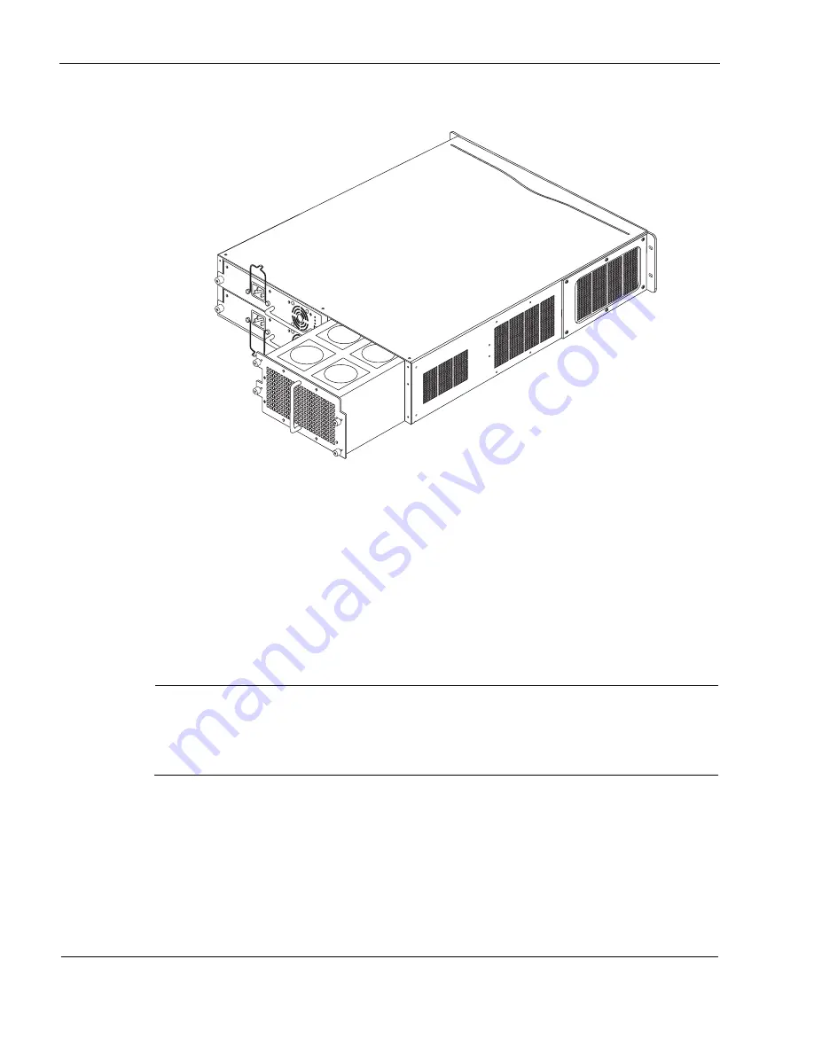
Slowly pull the fan unit out of the chassis toward the rear.
4.
If the IP2450 appliance is running, immediately install a replacement fan unit by sliding it
into the back of the appliance.
5.
Tighten the four retaining screws on the new fan unit.
Installing or Replacing a Power Supply
The power supplies in the Check Point IP2450 appliance are hot swappable, and perform load
sharing while two active power supplies are connected in parallel. Load sharing increases the life
of the power supplies.
Note
On an appliance with two active power supplies installed, both power supplies should be
turned on for load sharing and redundancy. If both power supplies are not turned on, the
Fault LED illuminates. For more information about the Fault LED, see
The power supplies are autosensing and can accept input voltages between 85 VAC and 264
VAC. The power supply output is regulated to a tolerance of ± 5 percent of the specified output
voltage.
Under certain circumstances, the power supplies feel hot to the touch. This happens when the
power supply is connected to AC power, but is not turned on. In this state the 3.3 V standby
00631
700
W
AC
FAUL
T
OVER
TEMP
PWR OK
70
0W A
C
FAUL
T
OVER
TEMP
PWR OK
Summary of Contents for Check Point IP2450
Page 6: ...6 Check Point IP2450 Security Platform Installation Guide ...
Page 8: ...8 Check Point IP2450 Security Platform Installation Guide ...
Page 10: ...10 Check Point IP2450 Security Platform Installation Guide ...
Page 14: ...2 About this Guide 14 Check Point IP2450 Security Platform Installation Guide ...
Page 128: ...A Technical Specifications 128 Check Point IP2450 Security Platform Installation Guide ...
Page 132: ...B Compliance Information 132 Check Point IP2450 Security Platform Installation Guide ...
Page 136: ...Index 136 Check Point IP2450 Security Platform Installation Guide ...


