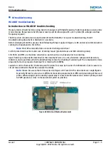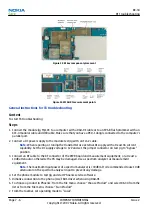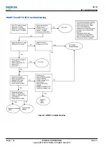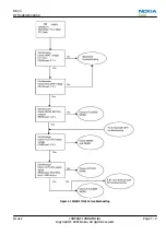
Introduction to WLAN RF tuning
Phone WLAN RF is tuned in production. There is no reason to do the re-calibration unlessoOne or more of the
RF components is changed.
Note:
RF calibration is always performed with the help of a product-specific module jig, never with an RF coupler.
Using an RF coupler in the calibration phase will cause a complete mistuning of the RF side.
Cable and adapter losses RF cables and adapters have some losses. They have to be taken in account when
the phone is tuned.
As all the RF losses are frequency dependent, the user have to be very careful and understand the
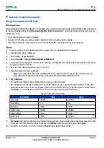
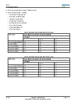
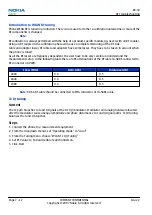
measurement setup. In the following table there are RF attenuations of the Rf cable CA-58 RS connected to
RF connector on PWB.:
Freq. (MHz)
Attn. (dB)
Tolerance (dB)
2400
0.4
0.5
2440
0.4
0.5
2480
0.4
0.5
Note:
XRS-6 RF cable should be connected to SMA connector of CA-58RS cable.
Tx IQ tuning
Context
The Tx path branches to I and Q signals at the RF I/Q modulator. Modulator and analog hardware located
after the modulator cause unequal amplitude and phase disturbance to I and Q signal paths. Tx IQ tuning
balances the I and Q branches.
Steps
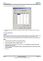
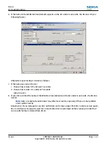
1. Connect the phone to a measurement equipment.
2. From the dropdown menus, set "Operating mode" to "Local"
3. From the Tuning menu, choose "WLAN Tx I/Q Tuning"
4. Set PCV value to 160 and Calibrate all channels on.
5. Click Start.
RX-34
RF Troubleshooting
Page 7 –12
COMPANY CONFIDENTIAL
Issue 2
Copyright © 2007 Nokia. All rights reserved.

