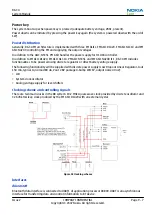
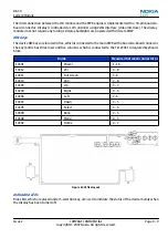
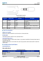
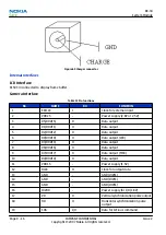
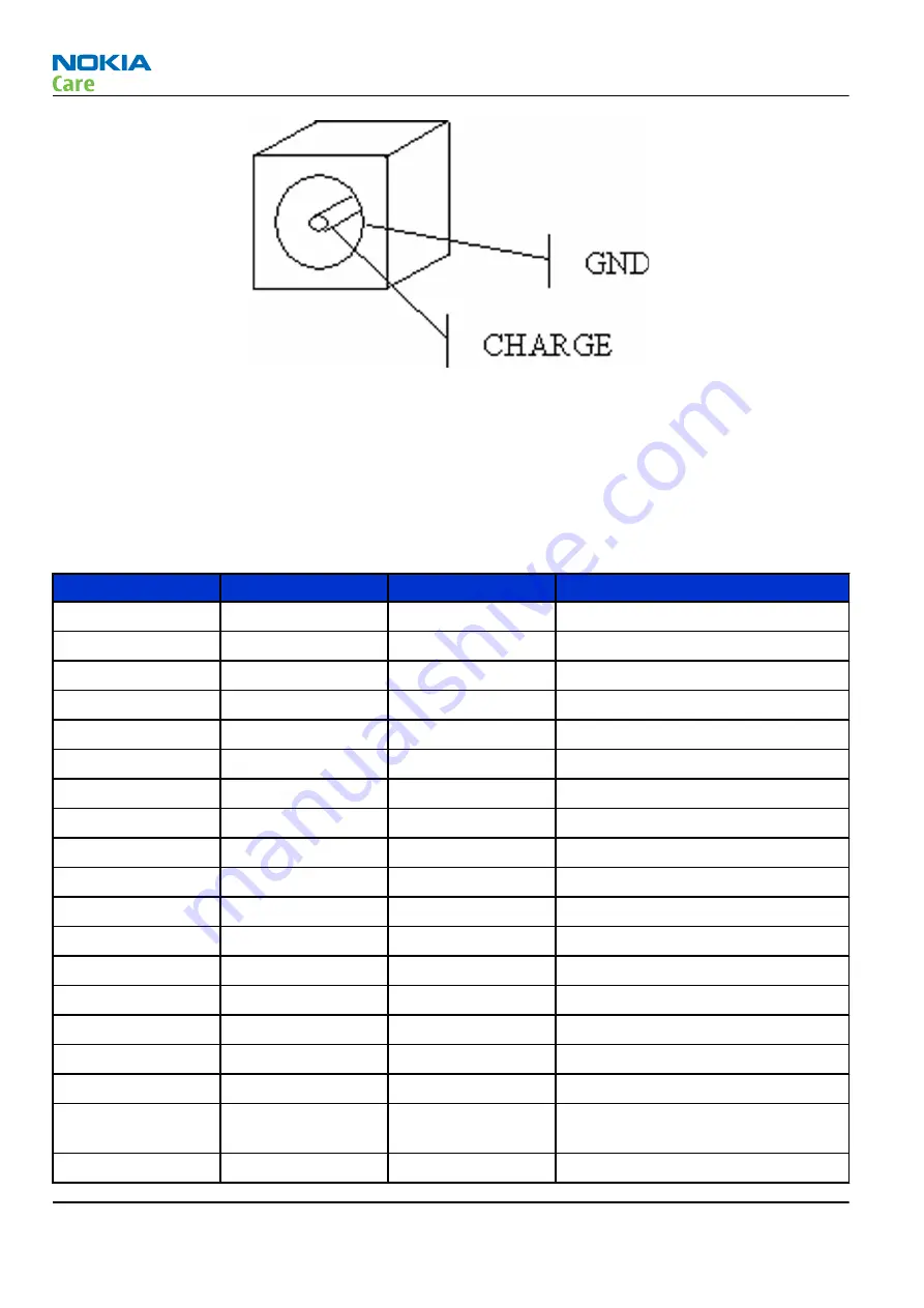
Figure 69 Charger connector
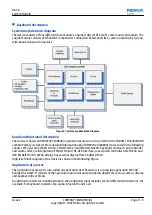
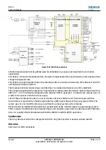
Internal interfaces
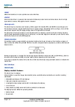
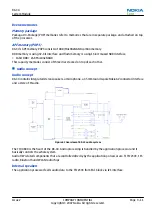
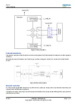
LCD interface
X1503 in connected to display frame buffer.
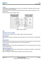
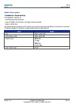
Camera interface
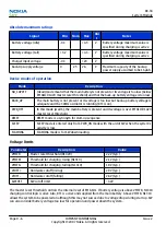
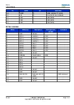
Table 19 Pin functions
No.
NAME
I/O
FUNCTION
1
EXTCLK
I
Clock for external input
2
VDD25
-
Power supply (2.8V or 2.5V)
3
D5(DOUT5)
O
Data output
4
D1(DOUT1)
O
Data output
5
D2(DOUT2)
O
Data output
6
D0(DOUT0)
O
Data output (LSB)
7
D3(DOUT3)
O
Data output
8
D6(DOUT6)
O
Data output
9
D7(DOUT7)
O
Data output (MSB)
10
D4(DOUT4)
O
Data output
11
VDD15
-
Power supply (1.5V)
12
DCLK
O
Clock for output data
13
GND
-
GND (IOVSS)
14
GND
-
GND (IOVSS)
15
GND
-
GND (IOVSS)
16
IOVDD
-
Power supply for I/O (1.8V)
17
VD
O
Vertical synchronization pulse output
18
HD
O
Horizontal synchronization pulse
output
19
SDA
I/O
Data for I2C-bus command
RX-34
System Module
Page 9 –16
COMPANY CONFIDENTIAL
Issue 2
Copyright © 2007 Nokia. All rights reserved.