Baseband description
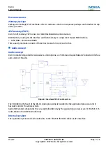
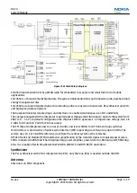
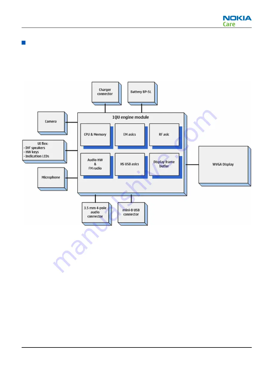
System module block diagram
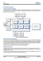
The device consists of four different main modules: engine (1QU), UI flex (1VY), camera and LCD module. The
engine module consists of BB and RF components. Connection between UI flex, camera and display is done
with board-to-board connectors.
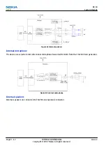
Figure 57 System module block diagram
Baseband functional description
The device is based on OMAP2420 (D4800) application processor on top of which the SDRAM / MuxOneNAND
combo memory is stacked. More detailed information about OMAP2420 (D4800) is presented in the following
chapter. EM asics are EM ASIC D1420, EM ASIC N1310 and EM ASIC N4200. Keyboard and touch pad controller
and audio codec are integrated in EM ASIC N4100. HS-USB interface goes via USB controller ASIC N5350 and
USB EM ASIC N5350. WVGA display has external display frame buffer D1510.
High level block diagram of the device is shown in thefollowing figure.
Application processor
The application processor is also called an application ASIC because it is processing application SW and
handles the UI SW. It consists of the application processor and peripheral subsystems such as camera, display
and keyboard driver blocks.
In addition to interfaces mentioned above, the peripherals block includes several different I/O interfaces, for
example, for keyboard, modem chip, audio, Bluetooth and so on.
RX-34
System Module
Issue 2
COMPANY CONFIDENTIAL
Page 9 –5
Copyright © 2007 Nokia. All rights reserved.


