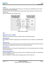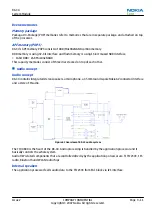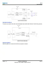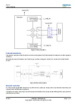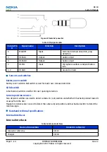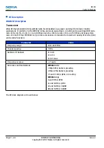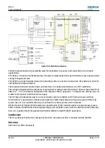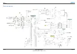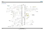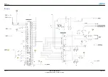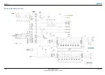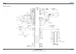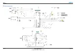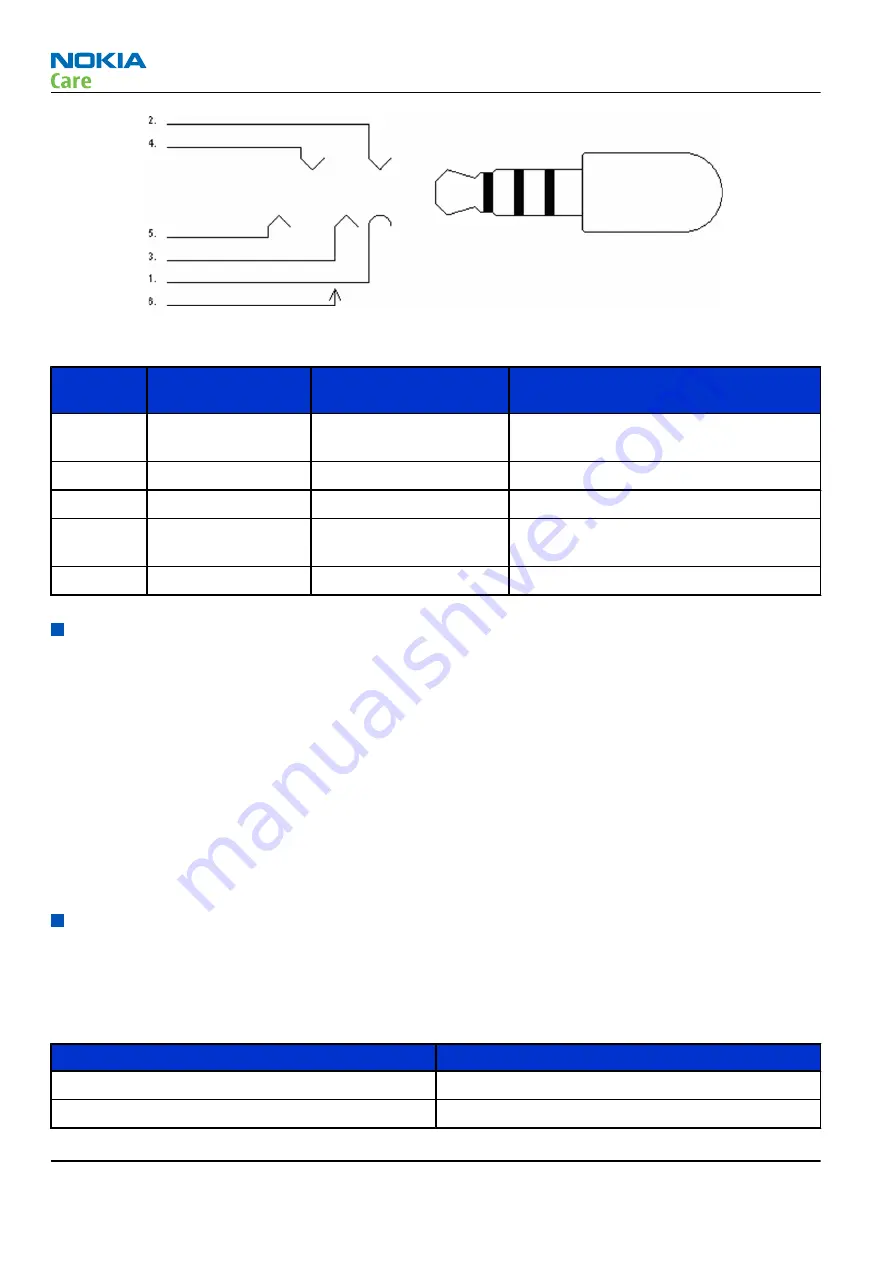
Figure 67 Nokia AV connector
Table 15 Pin/signal orders
3.5mm Pin
#
Signal name
Direction
Description
6
PLUGDET
Input
Terminal internal connection, plug
detection
5
HS EAR L
Output
Audio output
4
HS EAR R
Output
Audio output
3
HS MIC
Input
Microphone audio & send/end button
info
1, 2
HS GND
-
Ground contacts
Sensors and switches
Battery cover switch
Battery cover switch A Hall switch is used for back cover removal detection.
SD lid switch
A mechanical switch is used for SD cover opening detection.
Camera position sensors
Two detector switches are used to detect cameras in / out position and whether it has been pointed towards
or away from the user.
Magneto resistive sensor is used to detect the camera in/out position and mechanical switch to detect the
rotation angle.
Baseband technical specifications
External interfaces
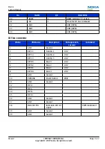
External interfaces
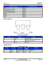
Table 16 External interfaces
Name of connection
Connector reference
Connector reference
X1110
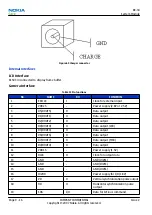
Charger
X1100
RX-34
System Module
Page 9 –14
COMPANY CONFIDENTIAL
Issue 2
Copyright © 2007 Nokia. All rights reserved.

