


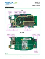
Nokia N97 mini
RM-553 / RM-555
Service Manual Level 1&2
21
Confidential
Copyright © 2009 NOKIA
All rights reserved
Version 1.0
ISSUE 1
12.
TOUCH PANEL RECALIBRATION
After replacing the RM-555/RM-553 A-Cover, the touch panel settings in the phone must be
recalibrated to match with the new touch panel
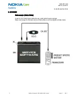
To perform this procedure, you will require the following equipment:
PC with Phoenix Service Software
USB Cable CA-101
FLS-5 Dongle
SS-93 Tool (or a stylus).
12.1
Recalibration setup
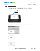
1.
Power on the phone, and boot to the home screen. (USIM is not required)
2.
Connect the phone to the PC via USB cable CA-101.
3.
On the phone, select “PC Suite Mode”.
4.
Ensure the PC has FLS-5 dongle connected.
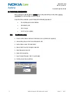
5.
Start Phoenix Service SW.
6.
Select USB connection.
7.
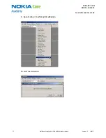
Scan Product (Phoenix > File > Scan Product)
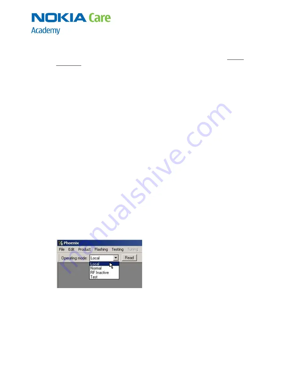
8.
Put the phone into Local Mode


