• Common mode voltage is a mean value of high and low states of one single-ended signal.
• Differential voltage swing is differential amplitude between signals of differential pair.
• Differential transitions should be only measured with good equipment (bandwith > 1GHz),
otherwise results will seem too slow.
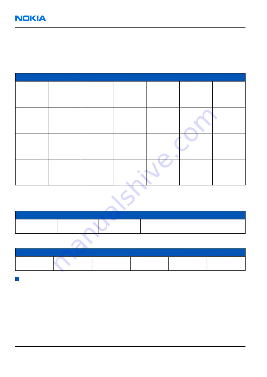
Table 32 Camera system regulators IF electrical characteristics
Description
Parameter
Min
Typ
Max
Unit
Notes
Vcam1V5
regulator
enable
VOH
V
Helen3 GPIO
High-level
output
voltage
Vcam1V5
regulator
enable
VOL
V
Helen3 GPIO
Low-level
output
voltage
Vcam2V8
regulator
enable
VOH
V
Helen3 GPIO
High-level
output
voltage
Vcam2V8
regulator
enable
VOL
V
Helen3 GPIO
Low-level
output
voltage
Back-up battery interface connections and electrical characteristics
Table 33 Back-up battery connections
Pin name
I/O
Connection
Notes
L2207, VBack
->
Retu, VBack
Back-up battery G2200 is connected to RETU via
coil
Table 34 Back-up battery electrical characteristics
Description
Parameter
Min
Typ
Max
Unit
Back-Up
Battery Voltage
Vback
0
2.5
2.7
V
RF description
Introduction to receiver functionality
Receiver functions are implemented in RF ASIC N7500.
The receiver is a linear direct conversion receiver consisting of separate front ends (LNA and demodulator) for
each supported system.
After the demodulators, the signal paths are combined to one common BB path.
RM-42
Nokia Customer Care
System Module
Page 9–46
Company Confidential
9241872 (Issue 1)
Copyright ©2005 Nokia. All Rights Reserved.


