6
4
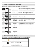
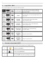
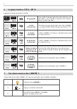
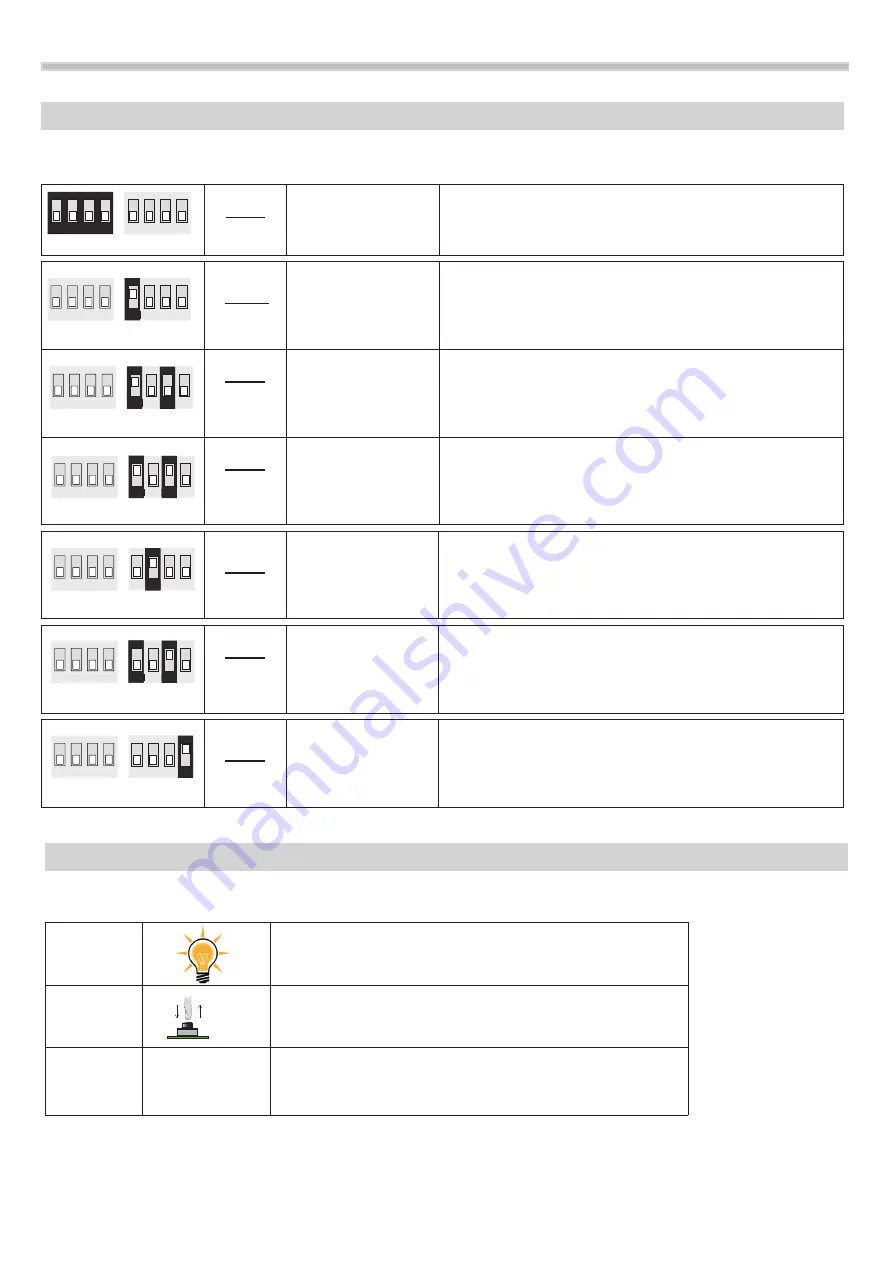
Logic DIP A - DIPB
We can see the function of the control unit with DIP A and DIP B:
1 2 3 4
1 2 3 4
DIP A
DIP B
DIP A
1-2-3-4
Bus Data System
you can enter the ID of the control unit with DIPA,
you can connect maximum 15 devices in the same
BUS DATA SYSTEM.
DIP B
1 ON
Twilight
If you put in oN you can have the twilight function in the
output LIGHT1.
DIP B
1 ON
3 OFF
Automatic
activation
The intput of LIGHT1 works forced activation,
when the contact is closed.
DIP B
1 ON
3 ON
Automatic
deactivation
The input LIGHT1 works in forced deactivation,
when the contact is open.
DIP B
2 ON
Recharge time
in the output
The STABLE function will be deactivated
in the timed outputs.
DIP B
1 OFF
3 ON
Activation
of the timing
LIGHT 1
Timing on the output LIGHT 1
DIP B
4 ON
Activation
of the timing
LIGHT 2
Timing in the output LIGHT 2
1 2 3 4
1 2 3 4
1 2 3 4
1 2 3 4
1 2 3 4
DIP A
DIP B
1 2 3 4
DIP A
DIP B
1 2 3 4
1 2 3 4
1 2 3 4
1 2 3 4
1 2 3 4
1 2 3 4
1 2 3 4
1 2 3 4
DIP A
DIP B
1 2 3 4
1 2 3 4
1 2 3 4
1 2 3 4
1 2 3 4
1 2 3 4
1 2 3 4
1 2 3 4
DIP A
DIP B
1 2 3 4
1 2 3 4
1 2 3 4
1 2 3 4
1 2 3 4
DIP A
DIP B
1 2 3 4
1 2 3 4
1 2 3 4
1 2 3 4
1 2 3 4
1 2 3 4
1 2 3 4
1 2 3 4
DIP A
DIP B
1 2 3 4
1 2 3 4
1 2 3 4
1 2 3 4
5
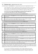
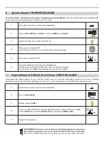
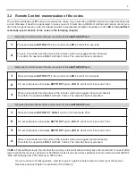
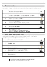
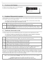
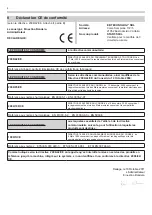
Function in the output LIGHT 3
Here you can change the function of the LIGHT 3 from standard use up to STABLE function:
1
Activate the output
LIGHT 3
2
Press and release
BUTTON
P1
3
If the output
LIGHT 3
is standard, it will stable and vice versa
P1


