


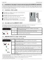


Making the correct choice of installation is essential to ensuring adequate safety and good protection against atmospheric
agents. Remember that the control unit contains powered parts and electronic components which by their very nature are
sensitive to infi ltrations and moisture. The control unit is supplied in a container which guarantees an IP55 protection rating
if adequately installed. Install the control unit on a permanent surface that is perfectly fl at, adequately protected against
impacts and at least 40 cm off the ground.
The cables must enter the control unit from the bottom only; we recommend using wire leads and water-tight connections.
When using tubing that could fi ll up with water or if the tubing comes from an underground well, the wires must enter a
first shunting box placed at the same height as the control unit and then, from there, the wires must be passed into the
container holding the control unit, again entering from the bottom. This prevents any evaporation of the water in the tubing
from forming condensation inside the control unit itself.
1.4 Preliminary checks
1 Introduction
START-S5PV
Technical manual
-4-
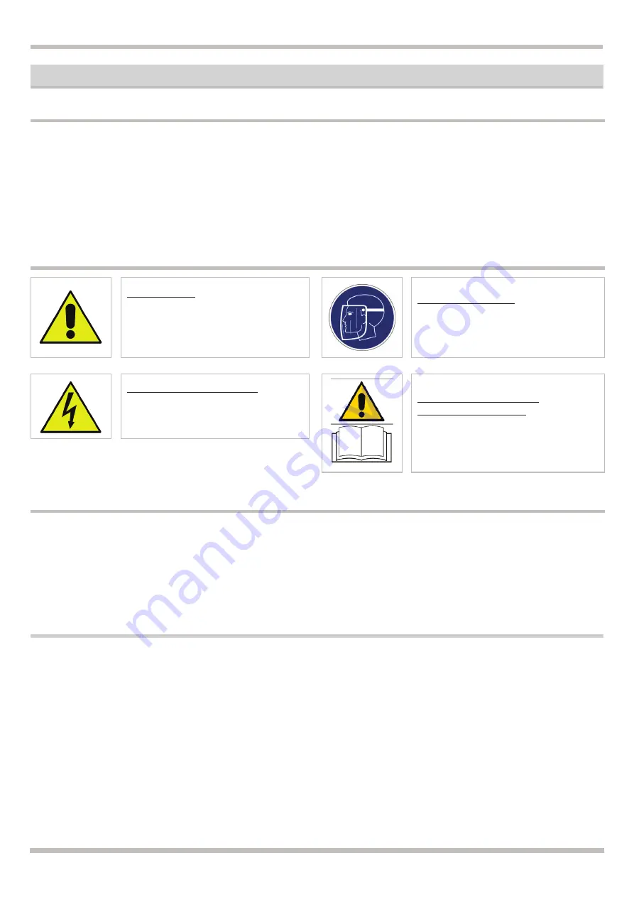
DANGEROUS
This is a warning and if it is not
respec it can provoque material dam-
age
DEVICE UNDER TENSION
The installation should be done only
from professional installer
Using the unit improperly and performing repairs or modifications personally will void the warranty. The producer declines
any responsibility for damages due to inappropriate use of the product and due to any use other than the use the product
was designed for. The producer declines any responsibility for consequential damages except civil liability for the products.
Remember that systems for automatic gates and doors must be installed by highly qualifi ed technicians only and in full
compliance with current law. Before starting installation, check that the mechanical consistency and sturdiness of the gate
or door, check that the mechanical stops are suitable to stop the movement of the gate or door even if the electrical limit
switches should fail or during manual operations.
1.1 Safety precautions
HEALTH DAMAGES
For safety reasons, protect your face
during the connection
READ CAREFULLY THE
OPERATING MANUAL
Read carefully this manul before in-
stallation and keep it for the future
1.2 Symbols and warning
1.3 Security system
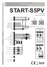
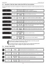
These two simple diagrams show only one of the possible applications for this control unit. The risks inherent to the
“MACHINE” and the user’s requirements must be analyzed in depth in order to establish how many elements need to be
installed.
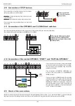
For a sure installation we suggest to install a STOP SWITCH, when it is working it stops immediatelly the door. The
SWITCH should have a normally closed contact and it opens when it is working (see Par. 3.10)


