background image

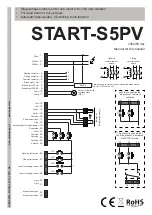
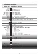
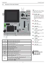
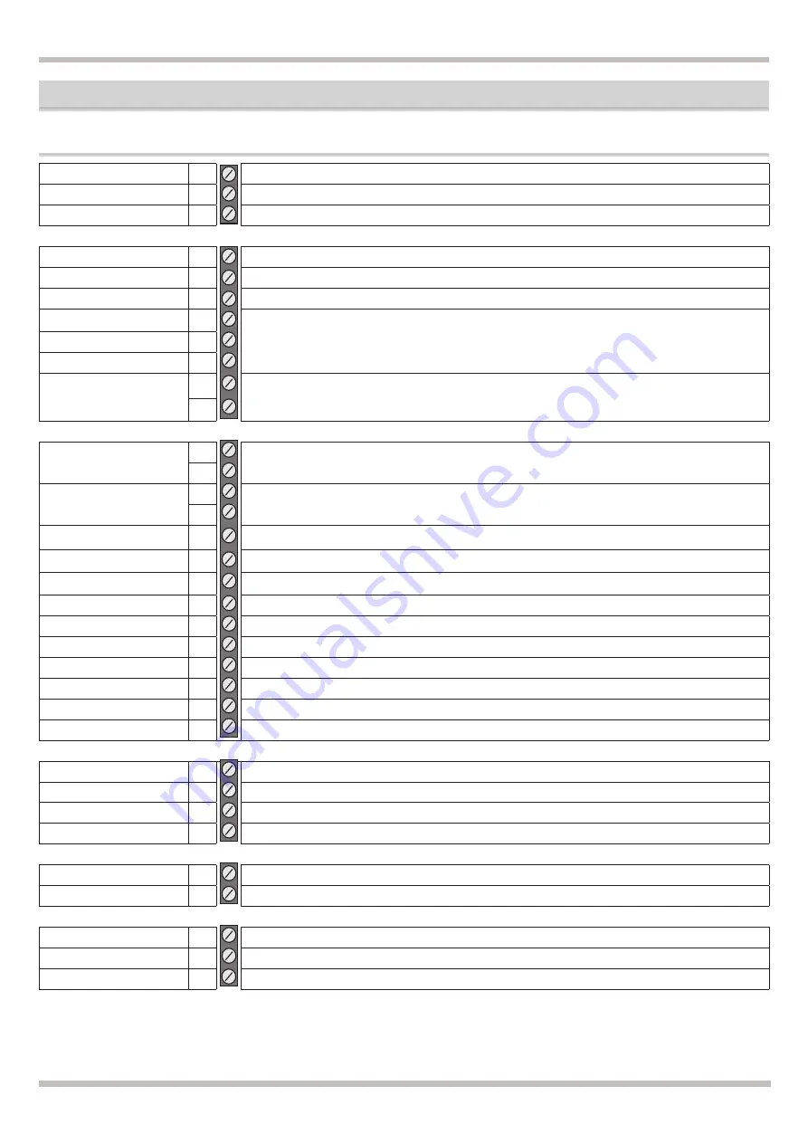
2.1  Description of the electrical connections

0 Vac 1

0 Vac

230 Vac 2

230 Vca 50 Hz power supply

400 Vac 3

400 Vca 50 Hz power supply

Opening contactor 4

Output for OPEN contactor

Closing contactor 5

Output for CLOSE contactor

Common contactor 6

Output for COMMON contactor

Common 7

Brake or a signal light (opening limit switch) 

can be connected to the terminal board no.7-8-9. 

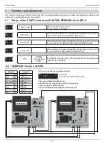
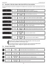
Use DIP B according to the instructions of Par. No.4.4

N.O. 8

N.C.  9

Lamp

10

Output for light or 230Vac courtesy light, maximum power for 100W lamp

11

Test

12

Isolated contact for PHOTO-TEST

13

24 Vac

14

Output 24 Vac

15

Common 16

Common contact for: services, safeties.
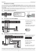
Photo-beam close 17

Input for photo-beam (the PHOTO will work only when closing)
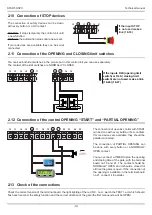
Stop 18

Input for STOP

Safety Edge 19

Input for SAFETY EDGE

Pedestrian 20

Input for PARTIAL OPENING

Start 21

Input for START control

Common 22

Common contact for: services, safeties

Common 23

Common contact for: services, safeties

Common 24

Common contact for: services, safeties, coaxial antenna cable

Antenna 25

+ Antenna

OLS 26

Input for OPENING limit switch

CLS 27

Input for CLOSING limit switch

Open 28

Input for OPEN

Close 29

Input for CLOSE

Isolated contact 30

Isolated contact for light

Isolated contact 31

Isolated contact for light

man present OPEN 32

Contact for “man present” OPEN

man present CLOSE 33

Contact for “man present” CLOSE

Common 34

Common

Installation of the control unit

START-S5PV

Technical manual

-6-

Summary of Contents for START-S5PV

Page 1: ...art 24 Vac 24 Vac 19 18 17 16 15 14 13 12 22 21 20 24 23 Common 24 Antenna Opening limit switch 26 Input for opening control 28 Input for closing control 29 Closing limit switch 27 BRAKE Passive brake...

Page 2: ......

Page 3: ...of the TENSION 8 2 4 Connection of the LAMP 2 5 Connection of a 24V light for working and opening gate 2 6 Connection of a CONTACTOR 2 7 Power supply to accessories 9 2 8 Connection of the PHOTO BEAM...

Page 4: ...ssional installer Using the unit improperly and performing repairs or modifications personally will void the warranty The producer declines any responsibility for damages due to inappropriate use of t...

Page 5: ...te must be installed in proximity to the control unit If the motors do not have a cable use the 4 x 1 5 mm2 cable open close common ground In connecting the part with an extremely low safety voltage u...

Page 6: ...for services safeties Photo beam close 17 Input for photo beam the PHOTO will work only when closing Stop 18 Input for STOP Safety Edge 19 Input for SAFETY EDGE Pedestrian 20 Input for PARTIAL OPENIN...

Page 7: ...indicates that the micro processor is ac tivated and it is waiting for con trols WARNING This control can be used only with limit switches 1 2 230 Vac power supply of the control unit 1 3 400 Vac pow...

Page 8: ...p without flashing light card DIP 7 OFF In case the lamp has a flashing light control card 2 5 Connection of a 24V light for working and opening gate 12 13 14 15 16 30 31 Terminal board 14 15 Power su...

Page 9: ...sed make a link 16 17 2 9 Connection of the PHOTO BEAM with PHOTO TEST 12 13 14 15 16 17 18 19 20 21 22 23 24 25 POWER SUPPLY TO TX PHOTOCELL POWER SUPPLY TO RX PHOTOCELL Photocell receiver N C contac...

Page 10: ...LY OPEN contact You can connect a TIMER to plan the opening and closing time of the gate with the terminal board no 16 and 21 The contact should be NORMALLY OPEN and it should e closed for all time th...

Page 11: ...1 ON 2 ON When opening and when closing the motors stop and the invert at the next control IT RECLOSE AUTOMATICALLY 3 ON Inhibits the opening control It inhibits the opening control if the photo beam...

Page 12: ...230V output for lamp 7 OFF Lamp with electronic card It activate the flashing light of the electronic card of the lamp 230 V output for lamp 8 ON Delay in referse It activate a delay of 2 seconds befo...

Page 13: ...l the led TEST start flashing 3 Wait until the led TEST starts flashing 15 seconds 4 3 MEMORIZATION of a single remote control The memorization of a code is possible when the gate is CLOSED ON CTS 2 1...

Page 14: ...ART or 16 20 for opening of PARTIAL OPENING see CONNECTION OF AN OPENING CONTROL and CONNECTION OF A PARTIAL OPENING CONTROL or from a memorized remote control see MEMORIZATION OF A REMOTE CONTROL The...

Page 15: ...AUSA 5 Press PARTIAL OPENING to start closing L automazione parte in CHIUSURA 6 Wait that the gate stopping automatically L automazione in posizio ne di CHIUSO 7 Put in OFF the micro switch no 5 of DI...

Page 16: ...START S5PV Technical manual 16 6 Note...

Page 17: ...er countries regarding electric materials for use within certain voltage limits Reference to harmonized standards EN 60335 1 89 336 CE EEC DIRECTIVE 89 336 CE ISSUED BY THE EUROPEAN COUNCIL on May 3 1...

Page 18: ...on est pr sent e sous la seule responsabili du constructeur et si applica ble de son repr sentant autoris Busto Arsizio Va Italia 31 03 2010 ERNESTINO BANDERA Administrateur KONFORMIT TSZERTIFIKAT Der...

Page 19: ......

Page 20: ...1052 Busto Arsizio VA Italia tel 39 0331 683310 fax 39 0331 684423 posta ebtechnology it www ebtechnology it NOLOGO S r l via Cesare Cant 26 20020 Villa Cortese MI Italia tel 39 0331 430457 fax 39 033...

Reviews: