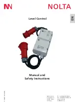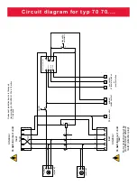
Circuit diagram for typ 70 71....
Blatt
Seite
processed
level control for float switch contection
MARKUS FISCHER
+
d
at
e
1
0
7
6
8
9
3
1
4
03.04.2020
Nolta GmbH
Industriestraße 8
35091 Cölbe
1
2
=
5
1 /
(optional)
(optional)
L1
L2
L3
N
PE
Phasenwender
(optional)
L1
L3
L2
L1
L2
A1
A2
13
14
1
2
3
4
5
6
L1
L2
L3
N
PE
14
13
T2
T1
PE
S1
S2
14
13
float switch
Attention!
Do
not
disconnect under
load!
feed
Overcurrent protection device in the suppl
y
line according to DIN VDE 0113 Part 1 Section
7.2 r
eq
uired.
On/Off
phase sequence
indicator
operating indicator
manually/
automatic
load
Attention!
Do
not
disconnect under
load!
Motor protection must be
provided via an external
motor protection plug!
external
switch contact
PE
level control
Summary of Contents for 70 703215
Page 10: ...Notes...

