background image


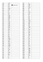
PART 
NUMBER 

VALUE  COMMENTS 

C1 

2n2 


C2 

2n2 


C3 

1nF 


C4 

1nF 


C5 

100p 


C6 

100p 


C7 

220nF 


C8 

100n 


C9 

100n 


C10 

100n 


C11 

100n 


C12 

470p 


C13 

10u 


C14 

10u 


C15 

10n 


C16 

100n 


C17 

1u 


C18 

10n 


C19 

10u 


C20 

100n 


C21 

10u 


C22 

100n 


C23 

100n 


C24 

100n 


C25 

100n 


C26 

1n 


C27 

10n 


C28 

1n 


C29 

10u 


C30 

10u 


C31 

10u 


C32 

1u 


C33 

1nF 


C34 

10n 


C35 

1u 


C36 

1u 


C37 

1u 


C38 

1u 


C39 

1u 


C40 

1u 


C41 

10u 


C42 

10u 


C43 

10u 


C44 

10u 


C45 

10u 


C46 

10u 


C47 

10u 


C48 

10u 


C49 

10u 


C50 

10u 


C51 

10u 


C52 

10u 


C53 

10u 


C54 

10u 


C55 

10u 


C56 

10u 


C57 

10u 


C58 

10u 


C59 

10u 


C60 

10u 


C61 

10u 


C62 

10u 


C63 

10u 


C64 

10u 


C65 

10u


C66 

10u


C67 

10u


C68 

10u


C69 

10u


C70 

10u


C71 

10u


C72 

10u


C73 

-


not on vers 2 

C74 

10u 


R1 

91k 


R2 

100k 


R3 

100k 


R4 

2M2 


R5 

24k 


R6 

10k 


R7 

56k 


R8 

1kT 

or thru-hole 

R9 

15k 


R10 

220R 


R11 

100k 


R12 

100k 


R13 

1k 


R14 

10k 


R15 

39k 


R16 

10k 


R17 

100k 


R18 

10K 


R19 

10K 


R20 

100k 


R21 

100k 


R22 

100k 


R23 

91k 


R24 

100k 


R25 

100k 


R26 

2M2 


R27 

24k 


Summary of Contents for Null-A2

Page 1: ...a patch cable into either jack the preset is disconnected a VCO1 pulse out state variable VCF input b VCO2 pulse out ladder VCF input c state variable VCF LP output VCA1 input d ladder VCF output VCA2 input e VCA1 output mixer f VCA2 output mixer g Mixer output headphone amp h ADSR output VCA1 CV input i Clock divider 8 output ADSR gate input j LFO 1 square output S H clock input k LFO2 triangle o...

Page 2: ... are all listed as 10uF these are for decoupling You can replace some of them close to ICs with 100nF if you wish but the ones near the power connector and close to the bottom edge of the PCB should all remain 10uF The LFOs and Sloth have been designed to work with 2 pin bipolar LEDs You can just install normal LEDs instead if you want to be boring The ADSR uses a regular LED RL in the value list ...

Page 3: ...1u C39 1u C40 1u C41 10u C42 10u C43 10u C44 10u C45 10u C46 10u C47 10u C48 10u C49 10u C50 10u C51 10u C52 10u C53 10u C54 10u C55 10u C56 10u C57 10u C58 10u C59 10u C60 10u C61 10u C62 10u C63 10u C64 10u C65 10u C66 10u C67 10u C68 10u C69 10u C70 10u C71 10u C72 10u C73 not on vers 2 C74 10u R1 91k R2 100k R3 100k R4 2M2 R5 24k R6 10k R7 56k R8 1kT or thru hole R9 15k R10 220R R11 100k R12 1...

Page 4: ...R71 150k R72 1k R73 100k R74 8k2 R75 1k R76 470R R77 12k R78 62k R79 2K7 R80 1K R81 1K R82 1K R83 1K R84 470K R85 470k R86 15k R87 330R R88 2K7 R89 1K R90 1K R91 12k R92 100k R93 47k R94 47k R95 1K R96 12k R97 47k R98 30k R99 47k R100 470R R101 470R R102 220k R103 68k R104 10K R105 10K R106 100k R107 330k R108 1k R109 100k R110 47k R111 47k R112 10k R113 22k R114 220k R115 2K2 R116 1K R117 10k R11...

Page 5: ...184 150K R185 56k R186 560K R187 47k R188 15K R189 47k R190 56k R191 22k R192 100k R193 47K R194 33k R195 1M optional see notes R196 1k R197 100k R198 100k R199 RL ADSR LED R200 1k R201 47k R202 330R R203 100k R204 10k R205 330R R206 47k R207 not on vers 2 R208 4M7 R209 330k R210 100k R211 100k R212 220R R213 2k2 R214 4k7 R215 1k R216 100k R217 RL LFO LED R218 2k2 R219 2k2 R220 2k2 R221 2k2 R222 2...

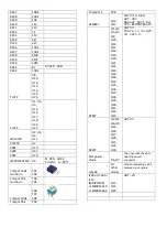
Page 6: ... Trimpot 20k multiturn TR2 TR4 Trimpot 100k TR6 TR7 TR9 Trimpot 50k TR5 Trimpot 1k TR8 BCM847 Q13 Q17 SOT23 6 AKA SOT 457 Mouser Part No 771 BCM847DS115 BC847 Q1 Q3 Q5 Q7 Q8 Q10 Q14 Q15 Q16 Q18 Q20 Q21 Q22 Q23 Q26 Q30 Q32 Q33 Q34 Q37 Q38 Q39 Q40 Q41 Q42 Q43 SOT23 There is no Q25 on vers 2 BC857 Q2 Q4 Q6 Q9 Q19 Q24 Q27 Q28 Q31 Q35 Q36 SOT23 S1JL power diode D6 D7 The ones with the dots near the pow...

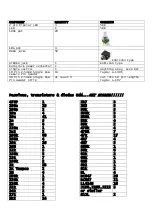
Page 7: ...ngle Row Pin Header Strip at least 4 cut into 10 pin lengths Tayda A 197 Passives transistors diodes BOM GET SPARES 470P 1 100n 10 100p 2 10n 4 10u 41 1n 5 1u 8 220n 1 2n2 2 100k 66 100R 4 10k 26 10M 1 12k 5 150k 5 15k 7 180k 2 1k 33 1k Tempco 2 1M 4 200k 1 220k 5 220R 4 22k 5 24k 2 27k 1 2k2 14 2k7 3 2M2 3 30k 3 330k 3 330R 3 33k 4 39k 2 470k 4 470R 7 47k 17 4k7 4 4M7 3 560k 1 56k 6 62k 2 68k 1 6...

Page 8: ......

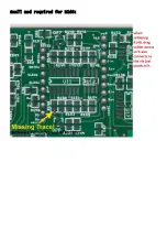
Page 9: ...Small mod required for R148 ...

Page 10: ... of the outputs is much louder than the other adjust this trimpot to get the outputs balanced TR6 the Freq offset trimpot is used to ensure the Freq pot is functional across its range same idea as the 100k trimpots on the VCOs Ladder VCF TR9 Ladder VCA trimpot at the top of the PCB is used to set up the VCA Plug in a signal and listen to the output Now plug a lead into the VCA CV input with the ot...

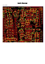
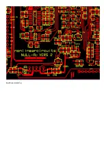
Page 11: ...Board close ups Top right ...

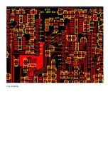
Page 12: ...Bottom right ...

Page 13: ...Top middle ...

Page 14: ...bottom middle ...

Page 15: ...Top left ...

Page 16: ...Bottom left ...

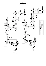
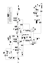
Page 17: ...SCHEMATICS ...

Page 18: ......

Page 19: ......

Page 20: ......

Page 21: ......

Page 22: ......

Page 23: ......

Page 24: ......

Page 25: ......

Page 26: ......

Reviews: