____________________________________________________________________________________
____________________________________________________________________________________
Speeder X1 and X2 Configuration and API Guide
Page 13/36
4 SPEED MEASUREMENTS
4.1 Speed measurement mode for vertical installation
The value of the Parameter 1 is 7.
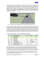
Fig. 1.
An example of speed measurement using Speeder X1 laser radar. Speeder X1 has two
separate laser beams A and B.
The geometry of the measurement is recommended to be >5:1 (please see the Fig. 1): For example, if the
sensor is at 5 m height it should be aimed to at least to 25 m distance in order to achieve good speed
measurement readings.
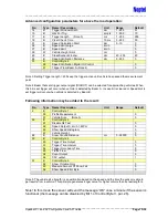
Fig. 2.
Default orientation of the Speeder X1 laser radar for vertical installation is laser radiation
sticker up. When orientation is changed parameter 53 must be set correspondingly.
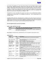
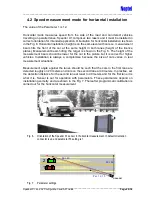
Setup in Fig. 1 and Fig. 3
applies for controlling of one lane per sensor. The sensor is aimed
at the centre of the lane for desired distance. Furthermore, the sensor comprises a laser
pointer, which can be used to set correct alignment. The laser pointer has poor visibility
at bright daylight and when used in fixed installation with a camera it is advised to align
the sensor with the camera at indoors. This enables the final aiming with the help of the
camera.
1
5
Speeder


